INSTALLATION MT86/MT86HT Flow Meter
4 Fluid Components International LLC
Prepare or Verify Flow Element Location
The flow element location has been previously determined before the time of order. Mounting the flow element in a position different than
originally determined may cause reading errors.
The shape of the flow element is cylindrical with a diameter of 2.00 inches (50.8 mm). The flow element length (U-length) is customer
specified. The recommended diameter for the clearance hole needed to mount the flow element is 2.16 inches (54.8 mm).
For the best performance, prepare an additional support for flow elements that are longer than 2 feet (61 cm). Refer to APPENDIX A, page
35, for specific information.
Verify Dimensions
Verify the customer specified flow element U-length and instrument mounting interface dimensions are correct for the application. Compare
the instrument hardware, APPENDIX A, page 35, and the process interfaces for fit.
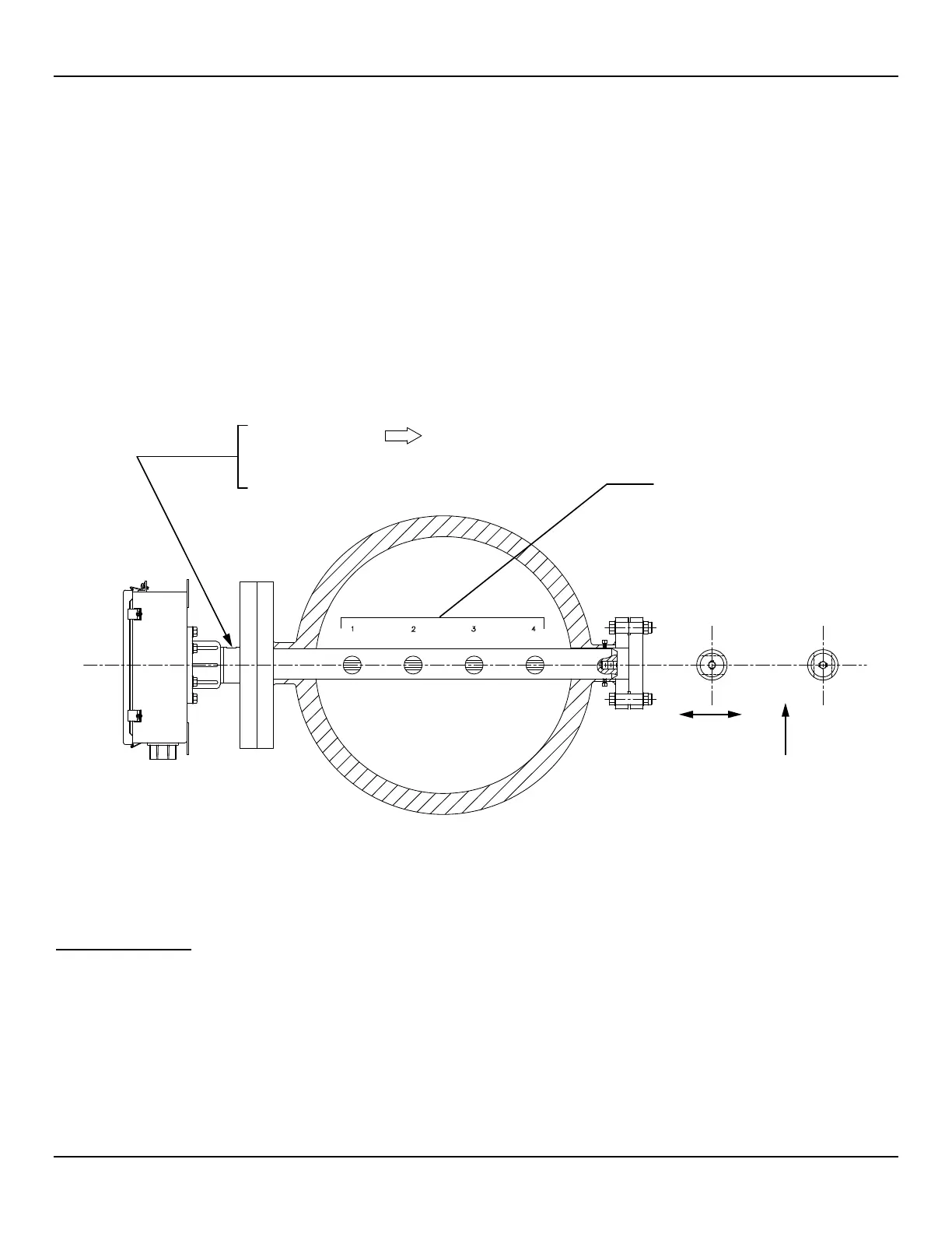
Verify Flow Direction for Flow Element Orientation and Placement
The flow element comes with a flat surface machined on the flow element near the enclosure. This flat surface is known as the Reference
Flat and includes a flow arrow etched on its surface to indicate flow direction. See Figure 2 for details.
Figure 2 –Flow Element Showing Flat Area, Flange Mount Shown
Align the flow element so the flat is parallel to the direction of flow. Also, align the flow arrow to point in the direction of flow. Failure to
correctly install the flow element reduces the accuracy of the flow meter. Refer to APPENDIX A, page 35, for specific information.
Install Flow Element
Install the flow element for the type of process connection used. If applicable, connect the end of the flow element to a recommended
mechanical support. See APPENDIX A, page 35, for installation details. The following are general steps for flow element installation.
Threaded Mount
When mounting the flow element, use a lubricant or sealant applied to the male threads of all
NPT connections. Ensure that the lubricant or sealant is compatible with the process
environment. Make sure all the process connections are tight. To avoid leaks do not over tighten
or cross-thread the connections.
VERTICAL
FLOW
APPLICATIONS
FLOW
HORIZONTAL
APPLICATIONS
C00277-1-1
NOMENCLATURE
ORIENTATION FLAT
PER APPLICATION
FLOW DIRECTIONARROW
FLOW"
PARALLEL TO
"THIS SURFACE
SENSING ELEMENT NUMBER