OPERATION MT86/MT86HT Flow Meter
14 Fluid Components International LLC
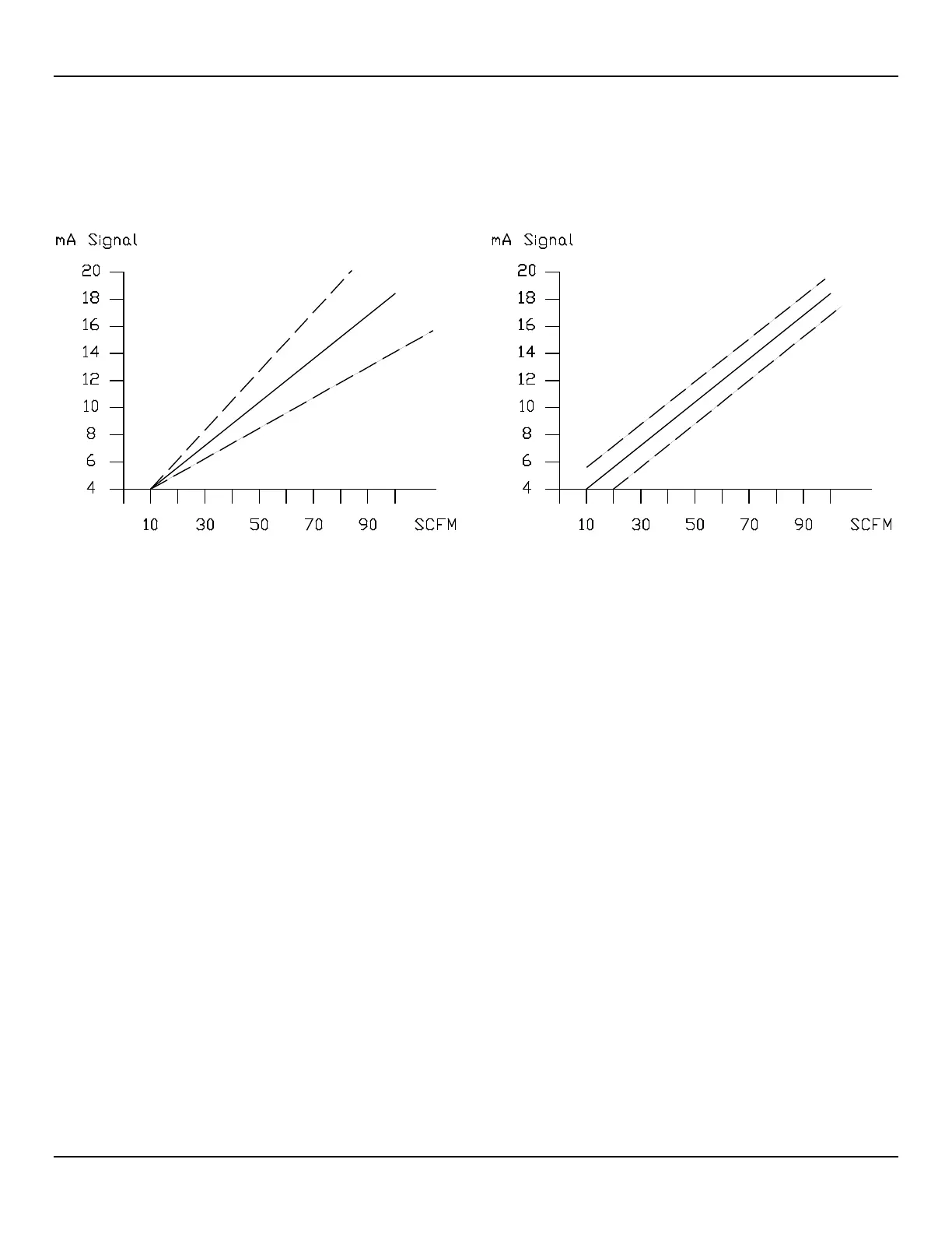
Table 2 shows the jumper settings that are needed to make the zero and span adjustments active. Figure 8 shows the zero and span
effects on the flow meter.
If only the zero adjust needs to be done, the span and zero jumpers will need to be set. Then proceed with the zero adjustment.
Figure 8 –Zero and Span Adjustment
If a span and zero adjustment cannot be done, the other choice for adjustment is an EPROM replacement. The EPROM stores the data
that represents the calibrated flow rate and the performance curve. FCI can provide a new EPROM with the new data and/or range. The
customer does have to provide FCI with Analog-to-Digital (A/D) information and the flow rate so the EPROM can be made. Look at the
Delta "R" table to get the A/D number. In the Delta "R" table, one column is categorized as Voltage In Non-Linear, [TP9 (+) to TP10 (-)].
Use the following equation to calculate the A/D number for the Non-Temperature Compensated flow meter only. Write down the results in
the chart shown in Figure 9.
A/D = ( [TP9 - TP10 (Vdc)]/2 )
X 5( 4096 )
For the Temperature Compensated flow meter, the A/D equation is:
A/D = [( [TP9 - TP10 (Vdc)]/2 )
X (4096)]/(TC Gain)
TC Gain is a function of the reference temperature. Additional data for the TC Gain is needed. This data is the REF SEN (+) to GND SEN
(-) voltage from terminal block TS#.
This A/D versus flow information is needed for each flow element sensing point in the flow meter.
FCI strongly recommends that as much data as possible be gathered because the calibration will be only as good as the data supplied.
Once a new EPROM is provided it will need to be installed (see the Repair procedure in TROUBLESHOOTING, page 19) and a new Delta
"R" table generated (see the preceding section for the procedure).
C00137-1
SPAN
ADJUST
ON POT R16 ZERO ADJUST ON POT R17