MT86/MT86HT Flow Meter TROUBLESHOOTING
Fluid Components International LLC 21
flash. The LED may also flash if there is no sensing point that corresponds to the switch position. If the Head-Select switch is pointing to a
valid sensing point and the LED is flashing the sensing point is bad.
Verify Resistance Readings
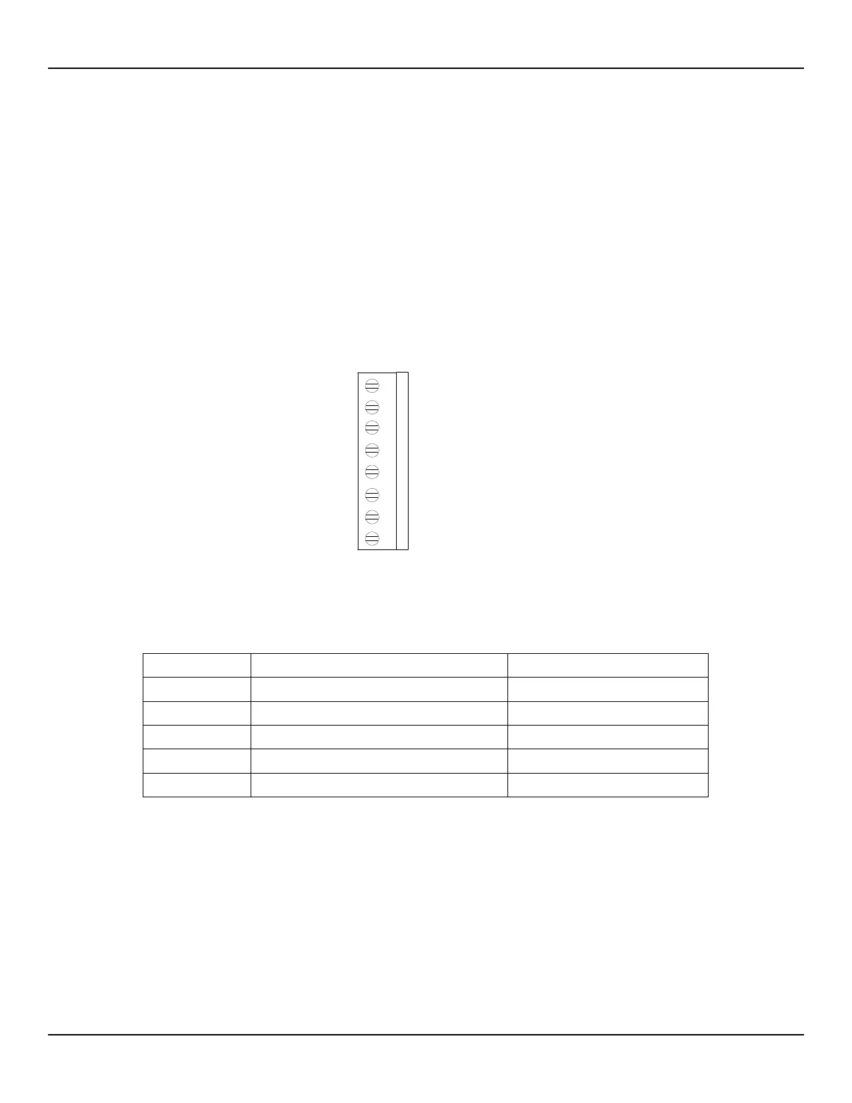
Use Figure 10 and Table 4 to determine if the flow elements are wired incorrectly or have failed. Turn the power OFF to the flow
transmitter. Unplug the problem flow element at the Input Board. Measure the resistances described below by touching the DMM test leads
to the terminal screws. (Remember to reconnect the flow element when the troubleshooting is finished.)
Note:
If the system process does not allow the flow meter power to be disconnected or the flow elements to be unplugged
then proceed to the Troubleshooting Process - Voltage Measurements section.
All resistances in Table 4 are based on a temperature of 32° F (0° C). Resistances across the ACT and the REF RTDs for an MT86 are
approximately 1000 ohms, resistances for an MT86HT are approximately 100 ohms. The resistances will continue to increase for higher
temperatures at the sensing points. Resistance values will vary with temperature.
Figure 10 – Terminal Plug
Table 4 – Terminal Plug Resistances
Approximate Resistance MT86/MT86HT
Approximate Resistance ST98
2 to 3 1000 Ohms* 1000 ohms
2 to 4 1000 Ohms* 1000 ohms
*For the MT86HT flow element divide by 10.
The resistance of the active RTD will be greater than the resistance of the reference RTD whenever the heater is on and the flow rate is
below the high-limit flow. Also if the flow meter has been on for some time, the resistance of the active RTD will be greater than the
reference until it cools down.
The flow element cable has a shield that ONLY connects to the flow transmitter side of the cable. There is no shield connected to the flow
element.
If one sensing point appears to be an open circuit and the other sensing point appears to be twice the resistance, a wiring problem
probably exists.
Voltage and current checks can be made on the flow elements. Before checking the flow element voltages and current, other voltages
need to be verified first. See the following paragraphs for the proper sequence of checks to make.
C00300-2-1
1 GND
2 GND SEN
3 REF SEN
4 ACT SEN
5 REF EXC
6 ACT EXC
7 HTR +
8 HTR -
TS1 OR TS2
CONTROL BOARD SIDE