MT86/MT86HT Flow Meter TROUBLESHOOTING
Fluid Components International LLC 25
If a voltage is missing, unplug all the input and output boards. Measure the voltage again to see if the voltage has returned. If it has
returned plug in the boards one at a time until the board is found that is loading the circuit. Remove and replace the board. If the voltage
does not return, replace the control board.
Flow Element Operating Voltages
Close switch SW1-1. Verify that all output signals go to the minimum signal level. Return switch SW1-1 to the open position after testing.
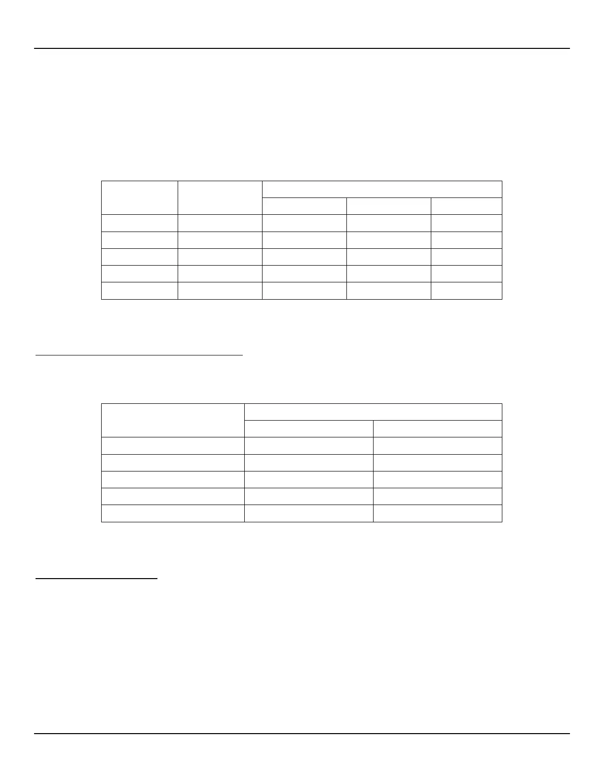
Make the following measurements at the input board terminal strip. See Table 7 and Figure 10 for the measurements.
Table 7 – Input Board Terminal Voltage Check
(+)
HTR + HTR - 16.5 VDC 16.5 VDC ± 1% 8.6 VDC
REF SEN GND SEN 1.10 VDC 0.275 VDC* 1.10 VDC
Note * The above readings are at 80°F (27°C) and 14.7 PSIA and at no-flow. The readings will vary with
temperature and flow. However, the reference voltages should always match and the active voltages
should always match. The active voltages should be higher than the reference voltages.
Troubleshooting Process - Flow Element Current
To measure the currents put a DMM in series with the desired lead. See Table 8 for the measurements.
Table 8 – Current Measurements
Component
Measured Value (mA DC)
HTR + 75.0 ±5% 75.0
If there are no problems, the flow elements are good. Further trouble shooting must concentrate outside of this area. Go to the following
sections.
Field Calibration Techniques
The flow meter circuit cards and the flow element can be replaced as separate items. A field calibration is needed after the replacement of
the parts.
Only qualified personnel should test or repair the instrument. The operator assumes all responsibilities for safe
practices while trouble shooting. Damage due to negligence or lack of technician skill is not covered by the warranty.
If field repair is attempted, replacement parts must be of the same part, type and number.