TROUBLESHOOTING MT86/MT86HT Flow Meter
22 Fluid Components International LLC
If the flow element is bad, replace it with a spare flow element. Return the bad flow element to FCI for repair and, or replacement. See
Appendix C for the Customer Service return procedure.
Troubleshooting Process - Voltage Measurements
Verify the use of the correct power source. Verify the power source is on and that the wiring matches the wiring diagram in Figure 3 in
INSTALLATION.
If the flow element resistance and wiring check out, recheck the power supply; the fuse and the AC and DC voltages.
If there are multiple failures in the flow meter, the power supply is suspect.
Perform the following voltage checks with power applied to the flow meter. Place the flow meter in normal operating conditions. Make all
measurements with the use of a DMM that has a differential (non-grounded) input.
Note:
The flow element sensing point voltage readings are for 1000 ohm RTDs.
Power Supply Source Voltages
Measure the power source at the power supply terminal block TS1 to be sure the correct power is applied.
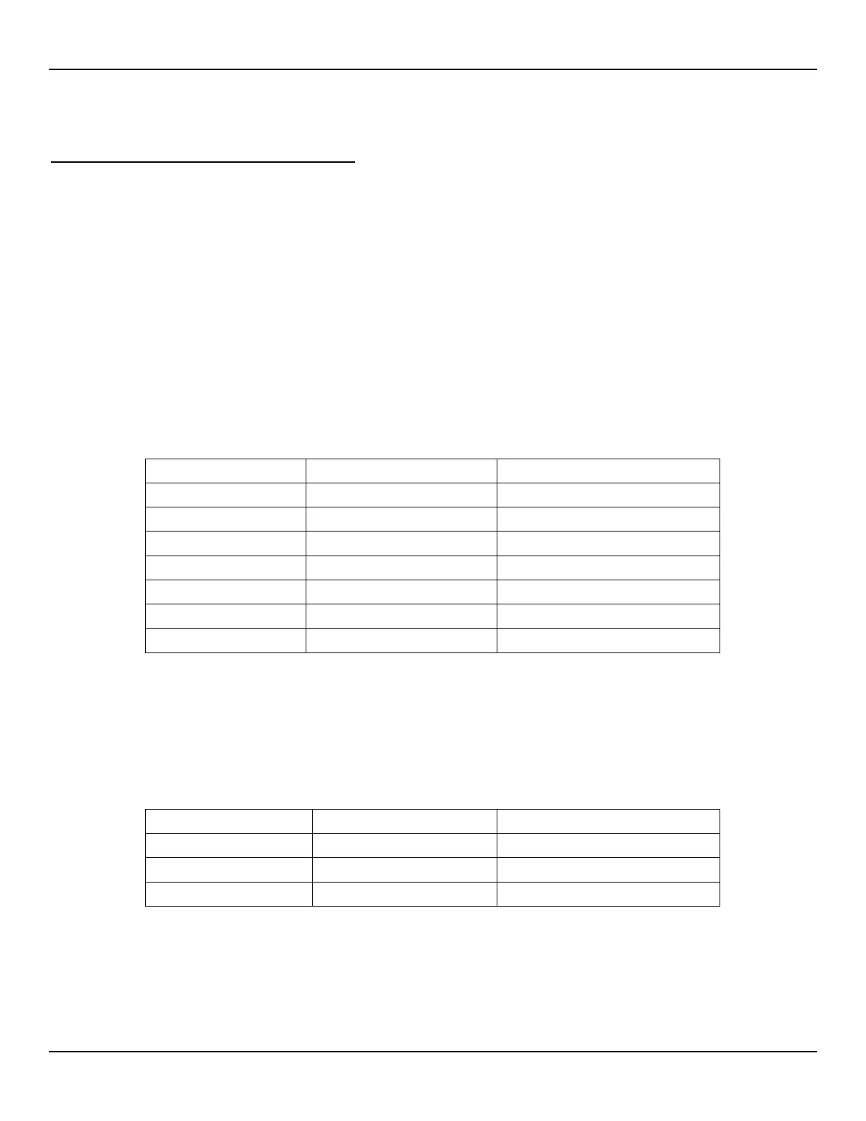
Check the power supply voltages, using the test points provided. See Table 5 and Figure 11 for the proper operating voltages. If the
voltage checks are correct, the power supply is functioning properly.
Table 5 – Power Supply Voltages, Power Supply Board
TP2 TP4 15 VDC ± .6 VDC
TP3 TP4 5 VDC ± .3 VDC
TP5 TP4 -5 VDC ± .3 VDC
*Measurement points are not available on some power supplies.
If operating power is at terminal block TS1 and the test points do not have power, check fuse F1 on the power supply board.
Remove power and unplug the power supply from the control board. Apply power to the power supply and re-measure the voltages as
shown in Table 6. If the voltage is still missing, then remove and replace the power supply.
Make the following measurements at the control board terminal strip. See Table 6 and Figure 12 for the measurements.
Table 6 – Power Supply Voltages, Control Board
Positive Lead (+) Negative Lead (-) Measured Value
TP15 TP16 10 VDC ± .02 VDC