TROUBLESHOOTING MT86/MT86HT Flow Meter
32 Fluid Components International LLC
8. When the sensor balancing procedure is completed, seal all adjusted potentiometers.
9. Turn the operating power OFF. Reconnect the heater circuit wires "HTR+" and "HTR-".
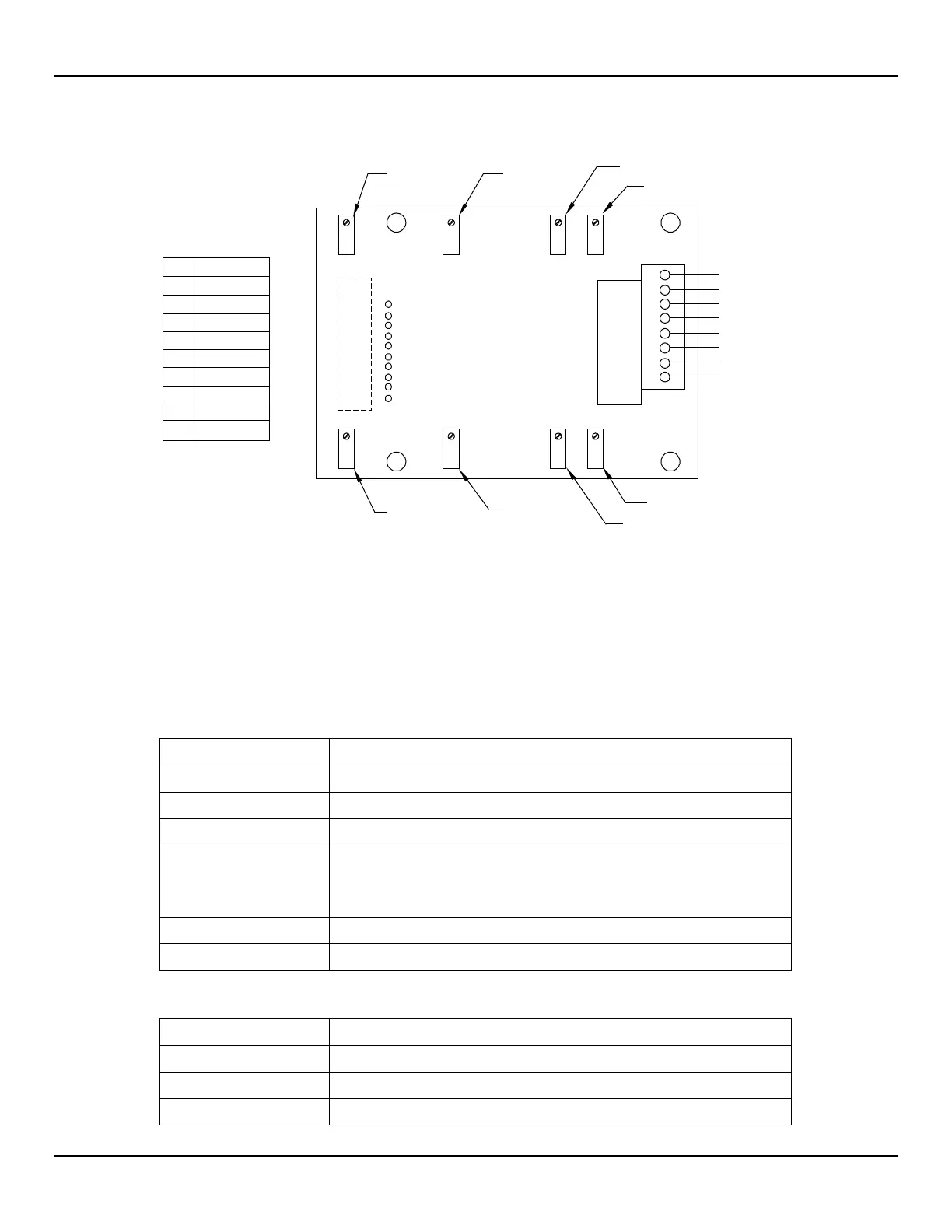
Figure 14 - Input Board
Spares
FCI typically recommends one or more complete sets of spare PWBs and flow element assemblies depending on how critical the
monitoring process is, as well as the FC81 field calibrators for convenience. Contact the field representative or FCI for specific
recommendations and part numbers. See Table 11 for spare parts and Table 12 for the recommended special test equipment. When
ordering the PWBs the part dash numbers also need to be given to the factory. The dash numbers can be obtained by looking at the
existing hardware or by looking at the Order Information Sheet that was filled out at the time the flow meter was ordered.
Table 11 - Recommended Spare Parts
Power supply board P/N 011528-XX or 012059-XX for DC
Control board P/N 01552-XX
EPROM with additional calibration (see factory)
Optional output modules: mA/DC voltage board P/N 011563-XX
Switch point board P/N 011581-XX
Remote board P/N 012576-XX
1 Input board P/N 011515-XX
1 Lithium battery (see factory for part number)
Table 12 - Recommended Special Test Equipment
Model FC81-8 field calibrator for MT86 (1000 ohm RTDs)
Model FC81-7 field calibrator for MT86 (100 ohm RTDs)
1 Document number 003169 – FC81 operating manual
ASS Y 011515-XX
ACT SEN
REF SEN
HTR -
HTR +
ACT EXE
REF EXC
GND
GND SEN
TS_
R4
R6
SEN BAL
1
HTR 2
SEN BAL 2
TS_
R3
R5
R9
R10
R17
R18
TC1 NUL
L
HTR 1
TC2 GAIN
TC2 NUL
L
3 4 65 108
972TP1
P_
T
P
TABLE
1
2
4
3
7
8
6
5
9
10
+ 15V
+ 28V
+ 5V
- 15V
+ 10V
SIG GND
TEMP
2
TC 2
TC 1
TEM
P
1