15
Connectors, Indicators, Controls, and Jumpers
Description, Specications, SSLoader + Software, and Operation Manual
Federal Signal www.fedsig.com
Connectors, Indicators, Controls, and Jumpers
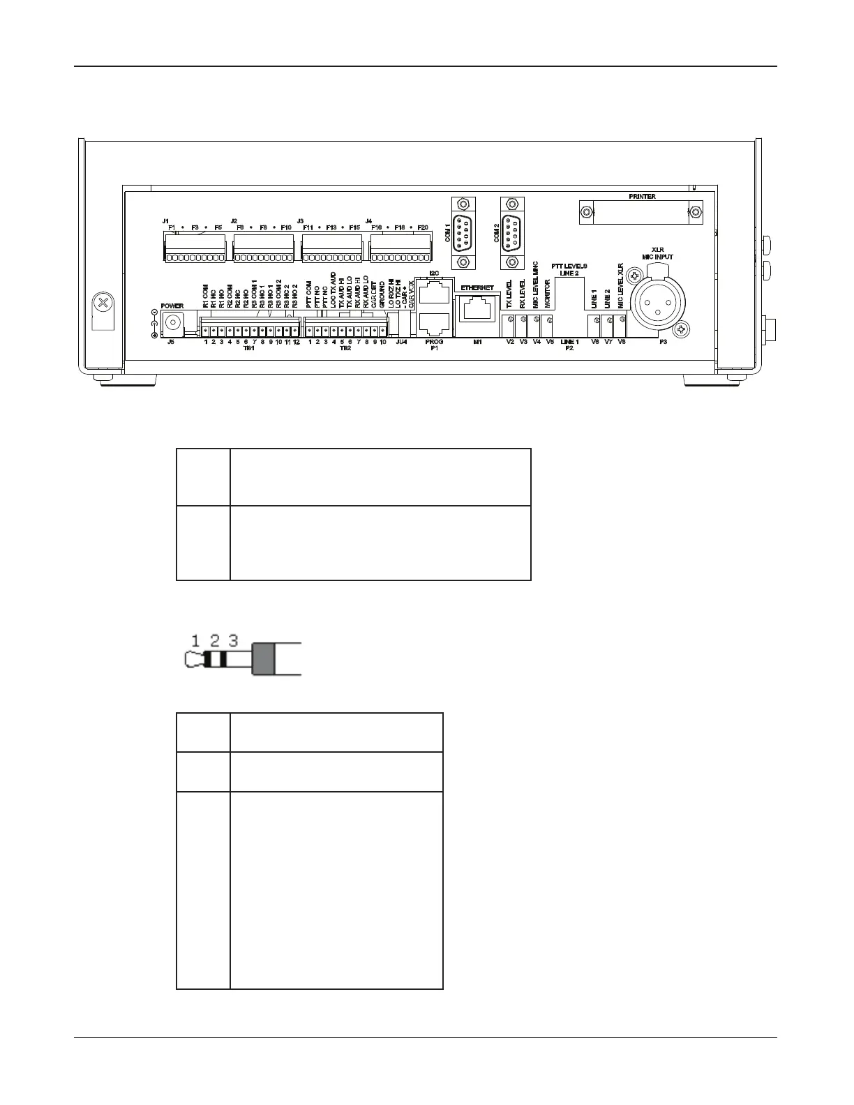
Figure 1 Drawing of the Back of the SS2000+
The following tables describe the connectors.
Table 3 Connectors
J5 DC Power In
Center – 12-30 Vdc input
Outside – GND
J6 Local Mic Input
1 – Mic audio
2 – PTT active low
3 – Ground
J6 is located on the side of the SS2000+ desktop and in front on the 19-inch rack.
P1
Upper
I
2
C Port
P1
Lower
Programming / FLASH Port
P2 Line Level Inputs
Top Tip – Input # 2
Top Ring – Input #2 PTT not
Top Shield – GND
Bottom Tip Input # 1
Bottom Ring – Input # 1 PTT
not
Bottom Shield – GND
1 – Mic audio
2 – PTT active low
3 – Ground
 Loading...