-34-
OnDTsystem,everyapartmentmustassignauniqueidenticationcalledUser Code.
There are two setting modes for address setting,DIP switcher and manual input .
Setting user code
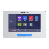
In default mode,when receiving a call,the master and slave monitors will ring at the same
time,and just the master monitor can display the image while the slave monitors will not. But the
settings can be changed,you can set the master monitor and all the slave monitors to panel on
at the same time when being called.
• Click “ Slave Panel On When Being Called” item,when “ “ symbol is displayed in the
frame , the setting is activated.
• Click the item again to cancel.
Setting slave monitor panel on
This monitor is assigned with DIP setting instructions.
OnAddresssettingpage,selectDIPSwitcherSetAddresssettingmoderstly,thentouch
icon, total 32 DIP codes will be displayed.
DIP Switcher Set Address
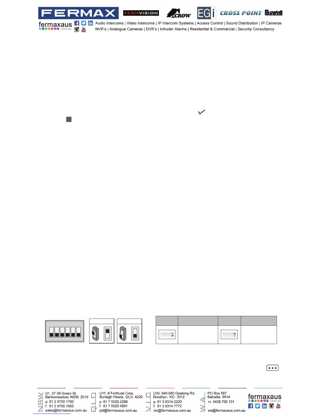
TheDIPswitchesareusedtosettheusercodeforeachmonitor.Total6bitscanbecongured.
• Bit-1 to Bit-5 are used for user code setting. The value range is from 0 to 31, which have 32
different codes for 32 apartments.
• When multi monitors need to be installed in one apartment, these monitors should use the
same user code, and the master/slave mode should be set on the monitor. (Details refer to
the section of Setting Slave Monitor)
• Bit-6 is bus line terminal switch, which should be set to “ON” if the monitor is at the end of
bus line, otherwise be set to “OFF”.
ON(1)
=
OFF(0)
=
ON
ON
ON DIP
1 2 3 4 5 6
Bit state Setting Bit state Setting
1 2 3 4 5
6
ON DIP
1 2 3 4 5
6
ON DIP
When monitor is not
at the end of bus line.
When monitor is at
the end of bus line.
Bit-6 switch setting