2 Installation as function module F24
28 Festo – P.BE-CPX-FB23-24-EN – 1305a – English
2.5.3 Pin allocation of the fieldbus interface
Bus connection
Socket Pin CC-LINK Designation
1
2
3
4
5
6
7
8
9
Housing
n.c.
DA
DG
n.c.
n.c.
n.c.
DB
n.c.
n.c.
SLD / FG
free (not connected)
Data A
Data reference potential (data ground)
free (not connected)
FE via R/C comb. (free)
free (not connected)
Data B
free (not connected)
free (not connected)
Cable screening/shield, connection to FE of the CPX terminal
Tab. 2.15 Pin allocation fieldbus connection
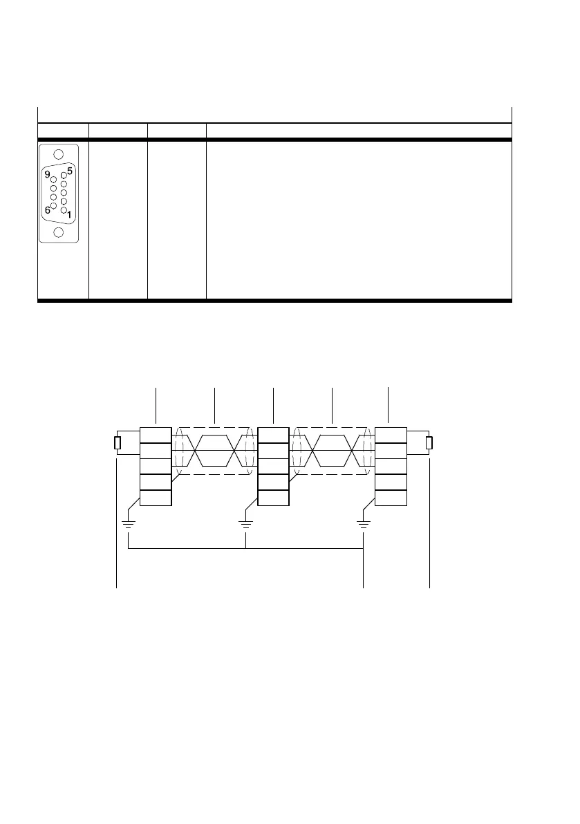
2.5.4 Connecting the fieldbus
Connection assignment
45
3
12
DA
DB
DG
SLD
FG
DA
DB
DG
SLD
FG
DA
DB
DG
SLD
FG
2
3
4
1 CC-Link master (master module)
2 Intended CC-Link cable
1)
3 CC-Link slave (Remote Device Station)
4 Terminating resistor
5 Earthing (SLD and FG connected in the
module)
1) The three cables for connection to BDA, CM and DG are twisted.
Fig. 2.4 Connection assignment of CC-Link

 Loading...


