3 Commissioning as function module F24
Festo – P.BE-CPX-FB23-24-EN – 1305a – English 37
3.2.3 Addressing examples (examples of address assignment)
General example
The following representations show t he address a llocation of the inputs and outputs with enabled
system diagnostics, different mapping optimisation (cycle time optimised or optimised station) and an
identical configuration of the CPX terminal:
16 DI, 24 DO, 10 AI, 8 AO.
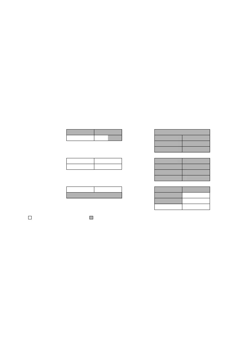
Mapping optimisation: optimised cycle time
The following configuration arises from the address capacity of the CPX terminal:
3 Stations, 1-fold cycle time.
Bit range Word range
RX
Inputs
RY
Outputs
RWr
Inputs
RWw
Outputs
Station 1 X1000
I15 … I0 O15 … O0 Y1000 D1000 System diagnostics (16 I/O) D2000
X1010 I31 … I16
O31
…O
16
Y1010 D1001 AI1 AO1 D2001
D1002 AI2 AO2 D2002
D1003 AI3 AO3 D2003
Station 2 X10²⁰ I47 … I32 O47 … O32 Y1020 D1004 AI 4 AO4 D2004
X1030 I63 … I48 O63 … O48 Y1030 D1005 AI5 AO5 D2005
D1006 AI6 AO6 D2006
D1007 AI7 AO7 D2007
Station 3 X1040 I79 … I64 O79 … O64 Y1040 D1008 AI8 AO8 D2008
X1050 Remote Ready ( RR = Bit 11) Y1050 D1009 AI9 AO9 D2009
D1010 AI10 AO10 D2010
D1011 AI11 AO11 D2011
Allocated address spaceAvailable address space
Fig. 3.1 Example for cycle time optimised CC-Link memory mapping