4 Diagnostics and error handling
Festo – P.BE-CPX-FB23-24-EN – 1305a – English 53
4.4 Diagnostics via LEDs
LEDs for the diagnostics of the CPX terminal are available on the bus node as well as on the individual
modules.
The meaning of the LEDs on the electric modules c an be found in the description for the
relevant module.
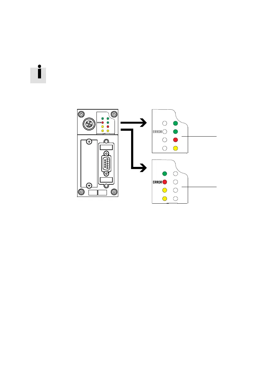
LEDs at the bus node CPX-FB23-24
The LEDs on the c over indicate the operating status of the CPX bus node.
PS
PM
SF
Run
SD
RD M
Run PS
PM
SF
M
SD
RD
PS
PM
SF
Run
SD
RD
M
1
2
1 CPX-specific LEDs:
– PS (green)
– PL ( green)
–SF(red)*)
– M (yellow)
2 CC-Link-specific LEDs:
– RUN (green)
– ERROR (red)
– SD (yellow)
– RD (yellow)
*) The SF LED a lso shows CC-Link-specific faults
Fig. 4.1 LEDs on the CPX bus node CPX-FB23-24
 Loading...


