A Technical appendix
Festo – P.BE-CPX-FB23-24-EN – 1305a – English 77
Fieldbus
Status information
–Protocol
–Version
– CC-Link chip
–Vendorcode
–Machinetype
CC-Link
Version 1.1 and 2.0
MFP3
0x0177
0x3C
Transmission speeds
(The maximum permitted field bus length de-
pends on the baud rate used, section2.5.2)
156 kBd, 625 kBd, 2.5 MBd, 5 M Bd, 10 MBd
Coupling and uncoupling during operation Yes (online-return function, slave station cut off
function)
Cable type
– Reference c able (Kuramo Electric CO.LTD)
– Alternative (LEONI Protec Cable Systems
GmbH, Art.No. L45467-Y19-C15)
– Terminating resistor
Cable specifica tion ( section 2.5.1)
FANC - 110SBH 0.5 mm
2
×3
CSFV110-SLAB (or corresponding cable according
to cable specification 1.1)
110 Ω / 0.5 W
A.2 Default parameterisation
Note
The following tables contain an overview of parameters of the bus node. The current
and detailed description of all parameters of a CPX terminal are found in the CPX system
description (P.BE-CPX-SYS-…) as well as in the description of each CPX module.
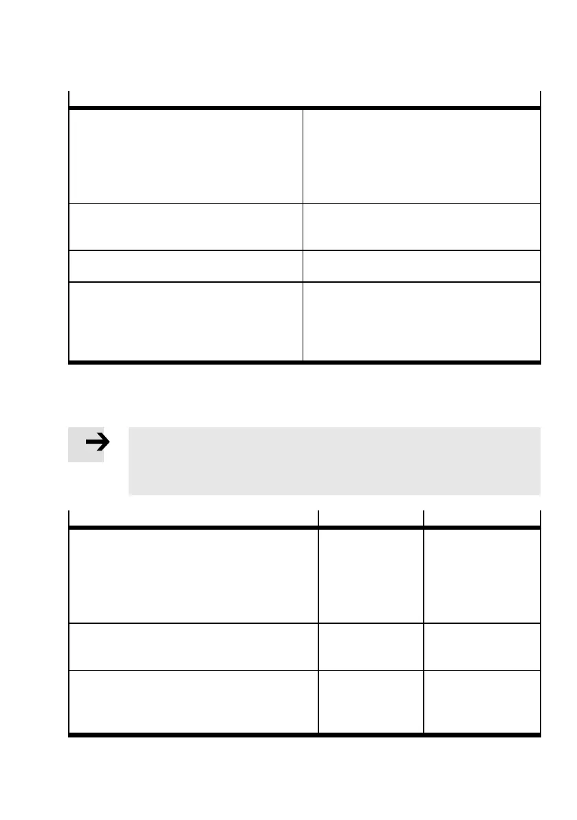
System parameters
Function no. Default s etting
Monitoring
– Short circuit/overload in sensor supply (SCS)
– Shor t c ircuit/overload at the outputs ( S CO)
– Undervoltage at the outputs (U
OUT
)
– Undervoltage at valves (U
VAL
)
– Short circuit at valves (SCV)
4401
active
active
active
active
active
Force mode
Defines whether the Force function is blocked glob-
ally or enabled.
4402 blocked
System start
Defines the starting reaction of the CPX terminal.
Saves current parameter settings.
4402 System star t with de-
fault parameterisation
(factory setting) and
current CPX expansion.
Tab. A.1 System parameters
 Loading...


