1. Summary of components
1−26
Festo P.BE−MPA−EN en 0910d
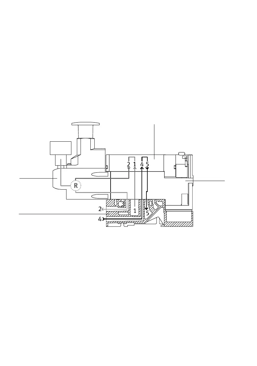
Fig.1/11 shows the following switching position of the B
pressure regulating valve:
The air is passed from channel (1) through the intermediate
plate and the valve to pressure regulating valve B, where it is
regulated and then passed to the port (2) of the sub−base.
The unregulated exhaust air is then fed via channel (4)
through the intermediate plate and then to channel (5) and
vented.
1
2
3
4
1 Pressure regulating valve
2 Valve
3 Intermediate plate
4 Sub−base
Fig.1/11: B pressure regulating valve
Mode of operation of the A pressure regulating valve:
Suppl y process:
The A pressure regulating valve regulate s the air pressure in
channel (4) after the pressure medium flow s through the valve.
The exhaust air is channelled through the intermediate plate and
switched from channel (2) to channel (3) in the valve.
Exhaust process:
During venting, the exhaust flow in the valve is unregulated
from channel (4) to channel (5) via the pressure regulating
valve.