MPS
®
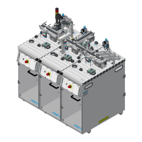
System 203 Basic
© Festo Didactic 8064034
45
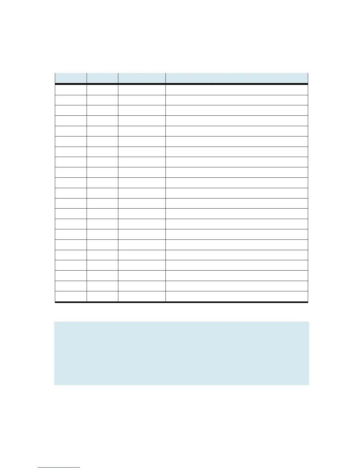
6.3.2 Terminal assignment table, Joining station (XG2)
Digital
Function SysLink Color Designation
I0 13 Gray-pink Slide retracted
I1 14 Red-blue Slide advanced
I2 15 White-green Gripper at bottom
I3 16 Brown-green Gripper open
I4 17 White-yellow
I5 18 Brown-yellow
I6 19 White-gray
I7 20 Gray-brown
Q0 1 White Retract slide
Q1 2 Brown Advance slide
Q2 3 Green Gripper up
Q3 4 Yellow Open gripper
Q4 5 Gray
Q5 6 Pink
Q6 7 Blue
Q7 8 Red
24 V A 9+10 Black 24 V power supply for outputs
24 V B 21+22 White-pink 24 V power supply for inputs
GND A 11 Brown-pink 0 V power supply for outputs
GND A 12 Purple 0 V power supply for outputs
GND B 23+24 White-blue 0 V power supply for inputs
Note
Cable jumpers are connected from emergency off to bit 1.5 for all standard PLC versions.
In the case of XG2, all signals are transmitted via a bus node which addresses the signals with
different protocols depending on the controller.
• For Siemens PLCs: ProfiNet,
• For Allen Bradley PLCs: Ethernet IP