MPS
®
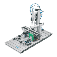
System 203 Basic
© Festo Didactic 8064034
59
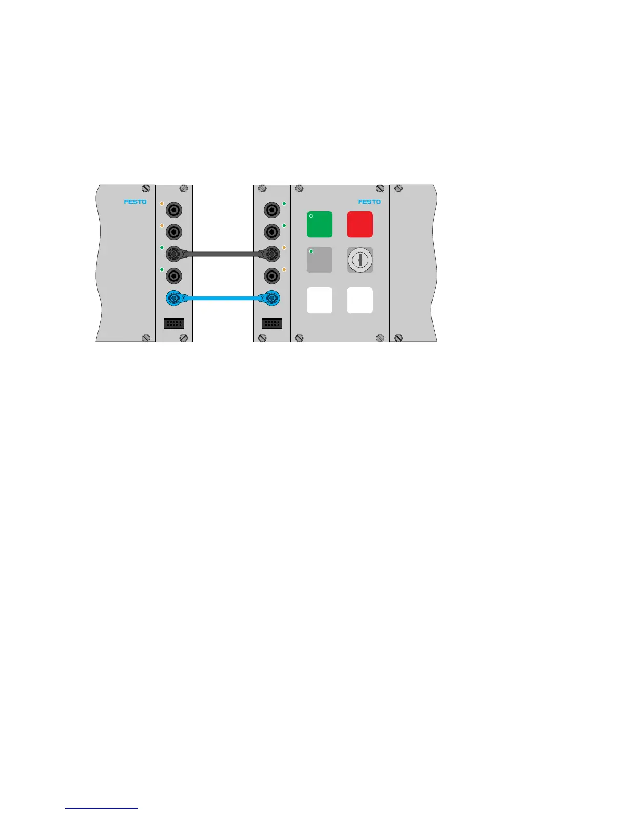
11.4 Establishing 1-bit communication links
The communication lines for use within the system are shipped loose and have to be plugged in.
Communication connections between the stations have to be set up in accordance with the following
example. The example is general but it applies to all stations. Any deviation from this standard will be
pointed out.
I/O
Q5
GND
Q4
I5
I4
Stop
Start
Reset
Auto/Man
Q1 Q2
I/O
I7
GND
I6
Q7
Q6
Example with I/O plug connections between control consoles: connect the Q4 and GND sockets of the downstream station to the I6 and
GND sockets of the upstream station.
11.5 Workstation
You’ll require the following in order to commission the MPS
station with the sample programs:
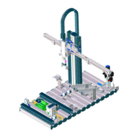
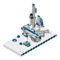
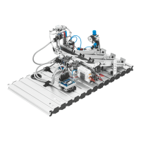
The assembled and adjusted MPS
®
station
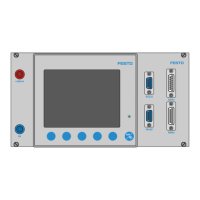
A control console
A PLC board with 16 digital inputs and outputs
A power pack: 24 V DC, 4.5 A
Compressed air supply: 600 kPa (6 bar)
A PC with installed PLC programming software and FCT software
Two I/O cables (SysLink)