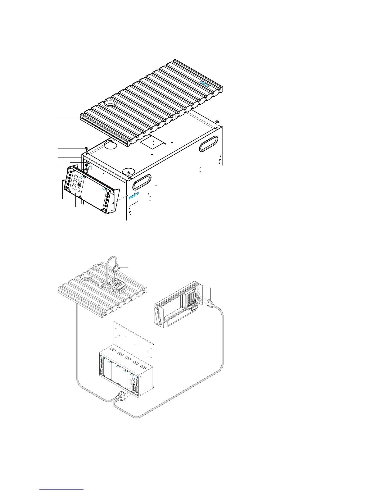
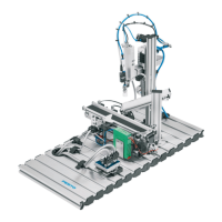
1 Profile plate
2 Hammer head nut, M6-32 (4 ea.)
3 Trolley
4 Serrated washer, J6.4 (4 ea.)
5 Washer, B-6.4 (4 ea.)
6 Socket head screw, M6x10 (4 ea.)
7 Sheet metal screw, 3.5x9 (2 ea.)
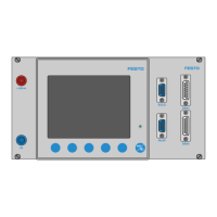
8 Control console
11.7 Cable connections
EMERGENCY STOP
C
AB
2
D
:M
P
4
-S
-
V
E
-
B
D
8
0
3
4
5
6
6
X
X
X
X
5
5
4
0
2
6
5
5
4
0
2
6
1
1
PLC board to station
If the SysLink 19" system plug module
is used: connect socket A to the SysLink
socket on the C interface using a
SysLink cable, or the SysLink socket at
the station’s digital I/O terminal.
2
PLC board to control console
If the SysLink 19" system plug module
is used: using a SysLink cable, connect
socket B to the SysLink socket on the
control console.
PLC board to power pack
Insert the 4 mm safety plugs into the
sockets on the power pack.
PC to PLC
Connect your PC to the PLC via a
programming cable.
PLC to bus node
Connect the PLC to the bus node using a
bus line.