Festo — MS6(N)-SV-...-E-10V24 — 2021-11e
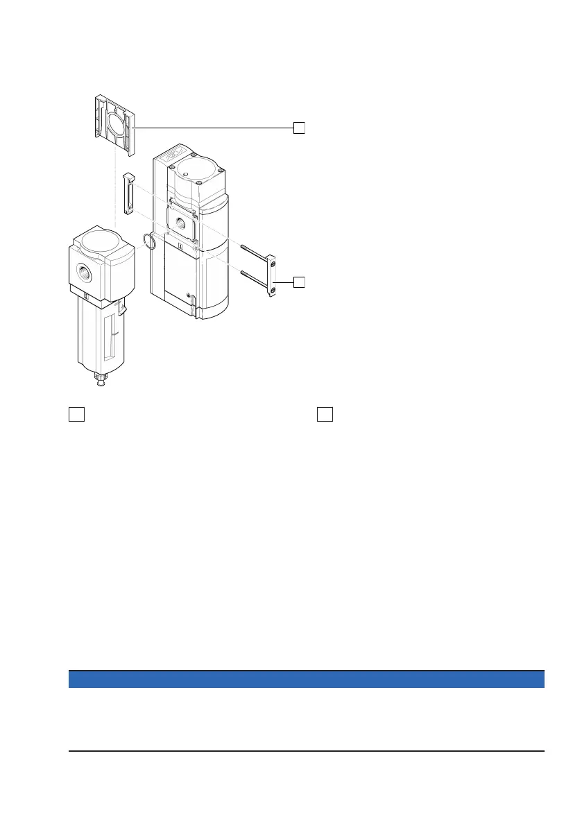
Fig. 15: Assembly
1
Cover cap MS6-END
2
Module connector
1.
Slide the cover cap MS6-END 1 upwards and remove it.
2.
Insert a seal 2 between the individual devices (module connector MS6-MV in scope of delivery).
3. Place module connector 2 in the slots of the individual devices.
4. Fasten the module connector with two screws (product scope of delivery). Tightening torque:
maximum 1.2 Nm.
6
Installation
6.1
Pneumatic installation
Port 1 and 2
If using screw connectors:
– Note the screw-in depth of the connector thread: 10 mm.
–
Make sure that the compressed air lines are connected correctly.
–
Screw the connectors into the pneumatic connections using a suitable sealing material.
Port 3
NOTICE
Failure of the safety function
Clogging of the cushioning body of an unsuitable silencer may result in reduced bleeding (back
pressure). This may result in failure of the safety function.
• Use the silencer UOS-... intended for the device exclusively.
 Loading...