Festo — MS6(N)-SV-...-E-10V24 — 2021-11e
12.7 Switching characteristics of the multi-pin plug sockets NECA-…-MP1,
-MP3 und -MP5
12.7.1 Switching characteristics for multi-pin plug socket NECA-S1G9-P9-MP1
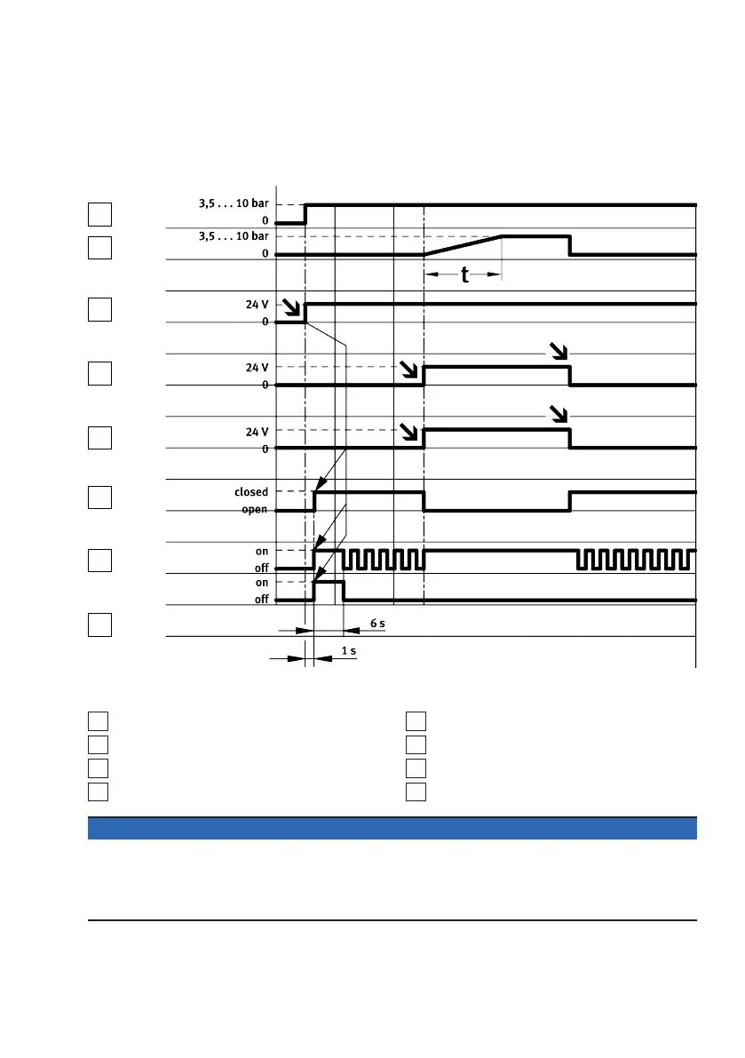
Fig. 20: Input and output switching characteristics in normal operation (when automatic start mode of
operation is set) for multi-pin plug socket NECA-S1G9-P9-MP1
1
Operating pressure p1
2
Outlet pressure p2
3
+L1: operating voltage
4
EN1: Enable signal 1
5
EN2: Enable signal 2
6
Signal contacts
7
Power LED (green)
8
Error LED (red)
NOTICE
• Pulses at inputs EN1 and EN2 from 0 to 24 V, of £ 3 ms duration do not send an error message to
the product.
• Pulses at inputs EN1 and EN2 from 24 to 0 V, of £ 12 ms duration do not send an error message to
the product.
The following diagrams shows the exact switching characteristics of the Enable signals EN1 and EN2
with time offset. The maximum reaction time can be derived from the delay between the two signals.
 Loading...