Festo — MS6(N)-SV-...-E-10V24 — 2021-11e
12.5 Filling flow
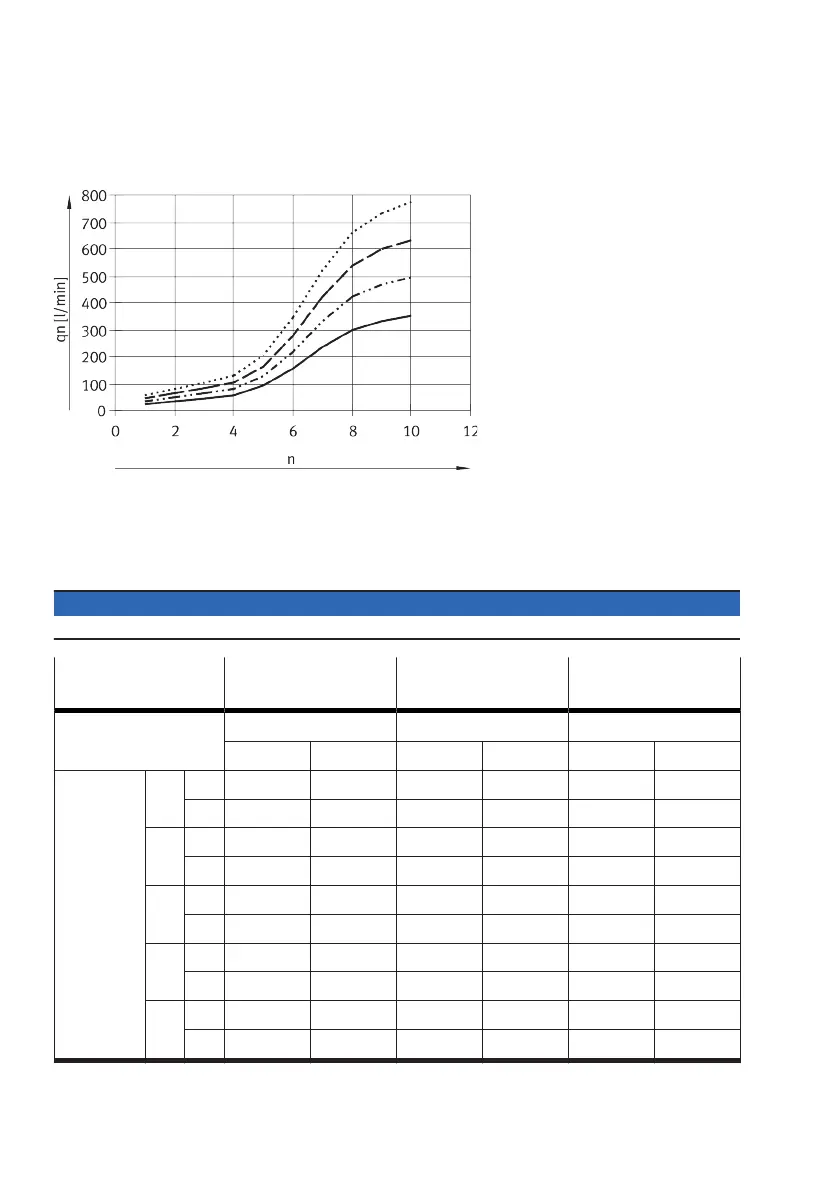
Flow rate qn dependent on the number of rotations n of the flow control screw
Fig. 19: Flow diagram
12.6
Exhaust time
The following table shows the exhaust time in normal operation (N) and in the event of a fault (F) for
different volumes and operating pressures.
NOTICE
In the case of a fault (F) the worst possible fault in the valve’s interior is assumed (worst case).
Normal operation: N
Fault case: F
Operating pressure
3.5 bar
Operating pressure
6 bar
Operating pressure
10 bar
Exhaust time [s] Exhaust time [s] Exhaust time [s]
to 1.0 bar to 0.5 bar to 1.0 bar to 0.5 bar to 1.0 bar to 0.5 bar
Volume [l] 2 N 0.1 0.2 0.24 0.3 0.3 0.4
(F) (0.16) (0.22) (0.28) (0.35) (0.36) (0.52)
10 N 0.3 0.45 0.55 0.7 0.7 0.9
(F) (0.4) (0.6) (0.8) (1.1) (1.2) (1.9)
20 N 0.5 0.85 1.0 1.3 1.4 1.7
(F) (0.8) (1.25) (1.5) (2.2) (2.4) (3.9)
40 N 1.2 1.9 2.2 3.0 3.0 3.9
(F) (1.7) (2.8) (3.4) (5.3) (5.1) (8.1)
150 N 3.2 5.0 6.0 8.2 11.0 12.8
(F) (4.8) (8.2) (9.8) (15.4) (16.2) (29.0)
Tab. 13: Exhaust time
 Loading...