Reproduction forbidden without Fibocom Wireless Inc. written authorization - All Rights Reserved.
L830-EB Hardware User Manual Page 17 of 39
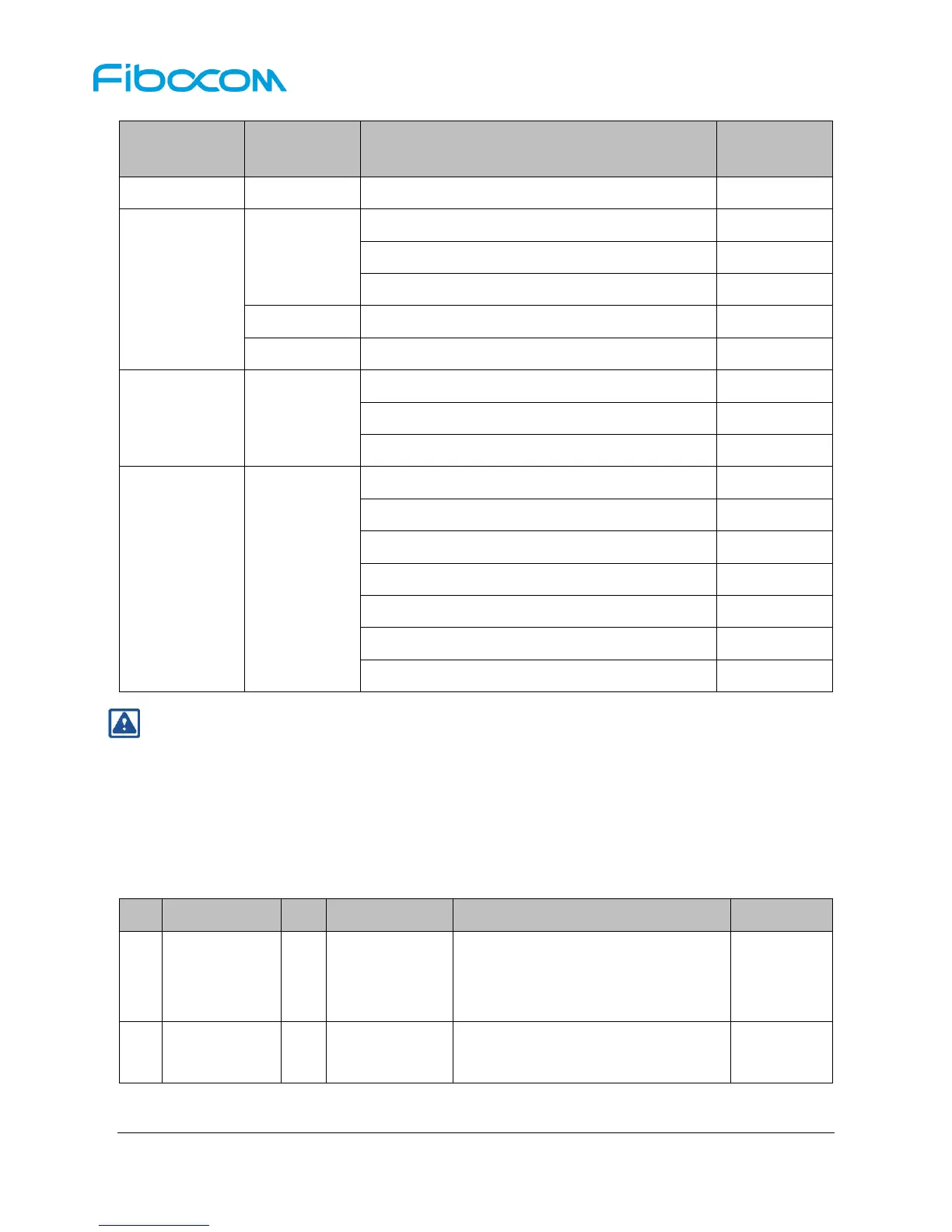
Power supply, module power off
Paging cycle #64 frames (0.64 sec DRX cycle)
WCDMA Data transfer Band I @+23.5dBm
WCDMA Data transfer Band V @+23.5dBm
WCDMA Data transfer Band VIII @+23.5dBm
LTE FDD Data transfer Band 1 @+23dBm
LTE FDD Data transfer Band 3 @+23dBm
LTE FDD Data transfer Band 5 @+23dBm
LTE FDD Data transfer Band 7 @+23dBm
LTE FDD Data transfer Band 8 @+23dBm
LTE FDD Data transfer Band 20 @+23dBm
LTE FDD Data transfer Band 28 @+23dBm
Note:
The data is the average of testing some samples.
3.3 Control Signal
The L830 module provides two control signals for power on/off and reset operations, the pin defined as
shown in the following table:
Power on/off signal
High: Power on
Low or floating: Power off
Reset signal, internal 100KΩ pull-up,
active low.