Reproduction forbidden without Fibocom Wireless Inc. written authorization - All Rights Reserved.
L830-EB Hardware User Manual Page 26 of 39
3.6 Status Indicator
The L830 module provides three signals to indicate the operating status of the module, and the status
indicator pins as shown in the following table:
System status LED, drain
output.
Module wakes up Host (AP).
3.6.1 LED#1 Signal
The LED#1 signal is used to indicate the operating status of the module, and the detailed description as
shown in the following table:
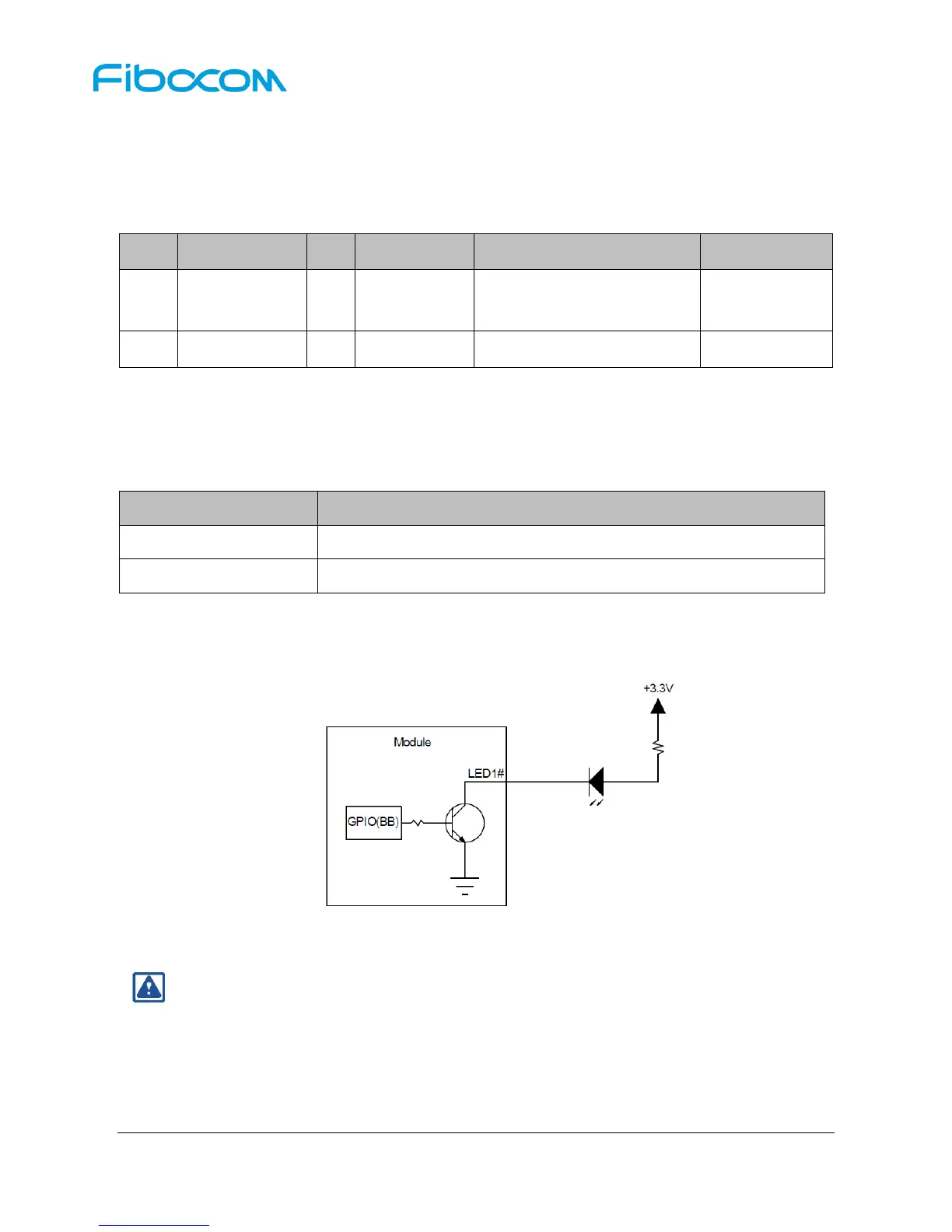
The LED driving circuit is as follows:
Figure 3-14 LED Driving Circuit
Note:
The resistance of LED current-limiting resistor is selected according to the driving voltage and
the driving current.