EasyManuals Logo

Fibocom L830-EB User Manual

Fibocom L830-EB
39 pages
To Next Page IconTo Next Page
To Previous Page IconTo Previous Page
Page #9 background imageLoading...
Page #9 background image
Reproduction forbidden without Fibocom Wireless Inc. written authorization - All Rights Reserved.
L830-EB Hardware User Manual Page 9 of 39
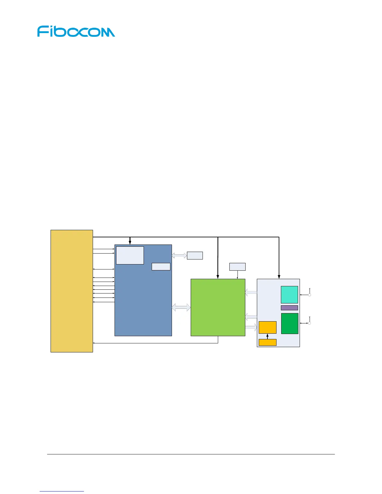
2.4 Hardware Framework
The hardware framework in Figure 2-2 shows the main hardware functions of L830 module, including
baseband and RF functions.
Baseband contains the followings:
UMTS/LTE FDD controller/Power supply
NAND/internal LPDDR2 RAM
Application interface
RF contains the followings:
RF Transceiver
RF Power/PA
RF Front end
RF Filter
Antenna Connector
+3.3V
FUL_CARD_POWER_OFF#
RESET#
USB2.0
USIM
EINT
WOWWAN#
LED
I2S
I2C
CLOCK
Tunable ANT
Baseband
(UMTS/LTE FDD controller)
PMU
TX
LPDDR2
RAM
NAND
Div
FEM
Main
FEMiD
PA DCDC
PA
RF Transceiver
RX
RX
RF Part
TCXO
M.2 Key-B 75pin interface
Div/GNSS
ANT
Main ANT
GNSS
Figure 2-2 Hardware Framework
3 Application Interface
3.1 M.2 Interface
The L830 module uses standard M.2 Key-B interface, with a total of 75 pins.

Questions and Answers:

Question and Answer IconNeed help?

Do you have a question about the Fibocom L830-EB and is the answer not in the manual?

Fibocom L830-EB Specifications

General IconGeneral
CategoryComputer Hardware
ManufacturerFibocom
ModelL830-EB
Form FactorM.2
Operating Temperature-10°C to +55°C
LTE BandsB1/B3/B5/B7/B8/B20
3G BandsB1/B5/B8
Data RateLTE Cat4: 150Mbps DL / 50Mbps UL
InterfacePCIe, USB 2.0
Operating Voltage3.135V to 4.4V

Related product manuals