Reproduction forbidden without Fibocom Wireless Inc. written authorization - All Rights Reserved.
L830-EB Hardware User Manual Page 21 of 39
Note:
The VSD2_1V8 signal is the internal PMU 1.8V output voltage which is not connected to the M.2
interface. The above timing of VSD2_1V8 is only for reference.
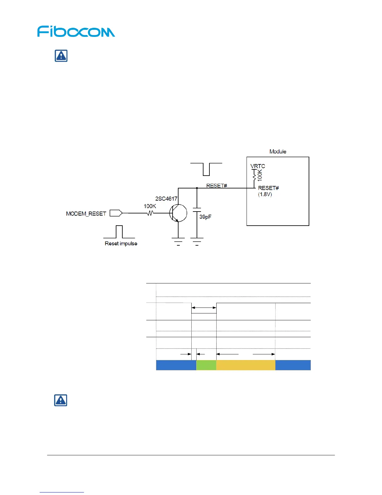
3.3.3 Module Reset
The L830 module can reset to its initial status by pulling down the RESET# signal for more than 10ms
(100ms is recommended), and the module will restart after the RESET# signal is released. When the
customer executes RESET# function, the PMU remains its power inside the module. The recommended
circuit design is shown in the Figure 3-9:
Figure 3-9 Recommended Design for Reset Circuit
The reset control timing is shown in Figure 3-10:
Figure 3-10 Reset Timing Control
Note:
RESET# is a sensitive signal, it’s recommended to add a filter capacitor close to the module. In
case of PCB layout, the RESET# signal lines should keep away from the RF interference and
protected by GND. Also, the RESET# signal lines shall neither near the PCB edge nor route on
the surface planes to avoid module from reset caused by ESD problems.