Reproduction forbidden without Fibocom Wireless Inc. written authorization - All Rights Reserved.
L830-EB Hardware User Manual Page 28 of 39
the RF radiation on the human body. The threshold of emission power can be set by the AT Commands.
The definition of DPR signal as shown in the following table:
The module keeps the default emission power
Lower the maximum emission power to the threshold value of the module.
3.8 Digital Audio
The L830 module supports I2S digital audio interface and it supports the ordinary I2S mode and PCM
mode. The signal level of the I2S interface is 1.8V. Please refer to “FIBOCOM Digital Voice” description
for detailed application design. The definition of I2S signals is as follows:
I2S left and right channel clock (LRCK)
.
3.8.1 I2S Mode
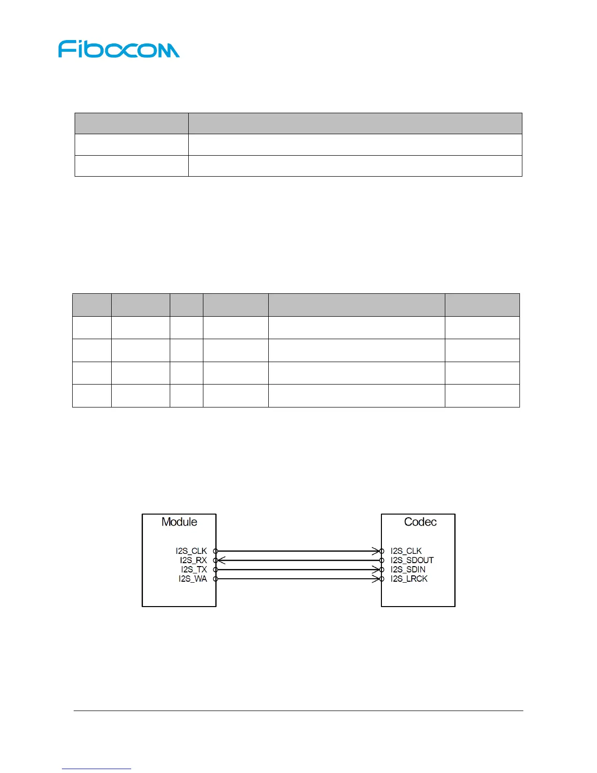
The L830 module is connected to the Audio Codec via I2S interface, and the codec encodes the audio
data to implement the voice call function. For the scenario, the module works as the I2S master, and the
codec works as the I2S slave. I2S signal connection is shown in Figure 3-18:
Figure 3-18 I2S Signal Connection
Description:
I2S interface can be configured as master or slave mode.
It supports multiple audio sampling rates (44.1KHz,32KHz,24KHz,16KHz,8KHz).
It supports 16bit and 32bit mode.