Audio Command Center Series Manual — P/N 51889:E1 6/8/2010 121
MS-5210UD Programmed Activation by FACP
ACC-25/50ZS and ACC-25/50ZST Switch Settings
ACC-ZPMK Zone Page Module DIP Switch S1
• Switches 1, 2, and 3 are set to OFF, OFF, OFF for No ACS link operation
• Switch 4 (future use) is set to OFF
• Switches 5, 6, 7, and 8 are set to OFF
ACC-ZSM Zone Splitter Module Switch Settings (refer to Section “ACC-ZSM Zone Splitter Mod-
ule (ACC-25/50ZS & ACC-25/50ZST)” on page 41 for additional information).
ACC-25/50ZS/T Main Board DIP Switch S3
The following DIP Switches can be set to any value except 1, 2, 3 = OFF, OFF, OFF.
• Switches 1, 2, and 3 are set to ON, OFF, ON for Single Zone output and the selection of five
messages
ACM-8RF Programming
• Set rotary switch on ACM-8RF for ACS address 1
• Assign SW3 DIP Switch settings per MS-5210UD manual
MS-5210UD Programming
• Assign functions (alarm, supervisory, etc.) to Zones 1 through 5 for voice message control.
• Enable the LED-10IM EIA-485 Interface Module.
MASTER
CMD OUT
TB6
1 2 3 4
+
+
--
+
+
+
+
-
-
-
-
1 2 3 4
1 2 3 4
CMD1
CMD2 CMD3
CMD4
CMD5
TB5 TB8
TB9
TB10
TB2
+
-
+
-
+
-
1 2 1 2
1 2
+
+
+
-
-
-
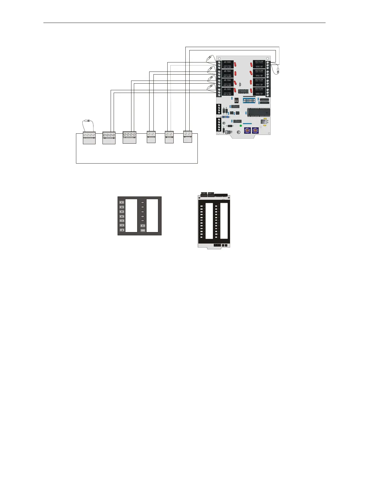
Figure D.4 ACC-25/50ZS/T Connection to ACM-8RF
4.7K ELRs, P/N: 27072
Connect CMD inputs of ACC-25/50ZS/T to
Normally Open relay contacts of the ACM-8RF.
ACC-25/50 Series Main Circuit Board
ACM-8RF
ACC-ZPMK
a
c
c
a
c
m
8
r
f
a
p
p
.
c
d
r
ALL-CALL
AUDIO
ON/OFF
FIRST ALERT
MESSAGE
TORNADO
MESSAGE
CHEM SPILL
MESSAGE
ALL CLEAR
MESSAGE
POWER ON
SYSTEM
TROUBLE
MESSAGE
TROUBLE
GENERATOR
TONE
GENERATOR
TROUBLE
RECORD
PLAYBACK
TROUBLE
SILENCE
MICROPHONE
TROUBLE
ZONE 1
ZONE 2
ZONE 3
ZONE 4
ZONE 5
ZONE 6
ZONE 7
ZONE 8
FACP Comm
ACC Comm
(Alarm Polarities Shown)