54 Audio Command Center Series Manual — P/N 51889:E1 6/8/2010
Installation Output Circuits
3.6.6 ACC-ZSM Zone Splitter Module (ACC-25/50ZS & ACC-
25/50ZST)
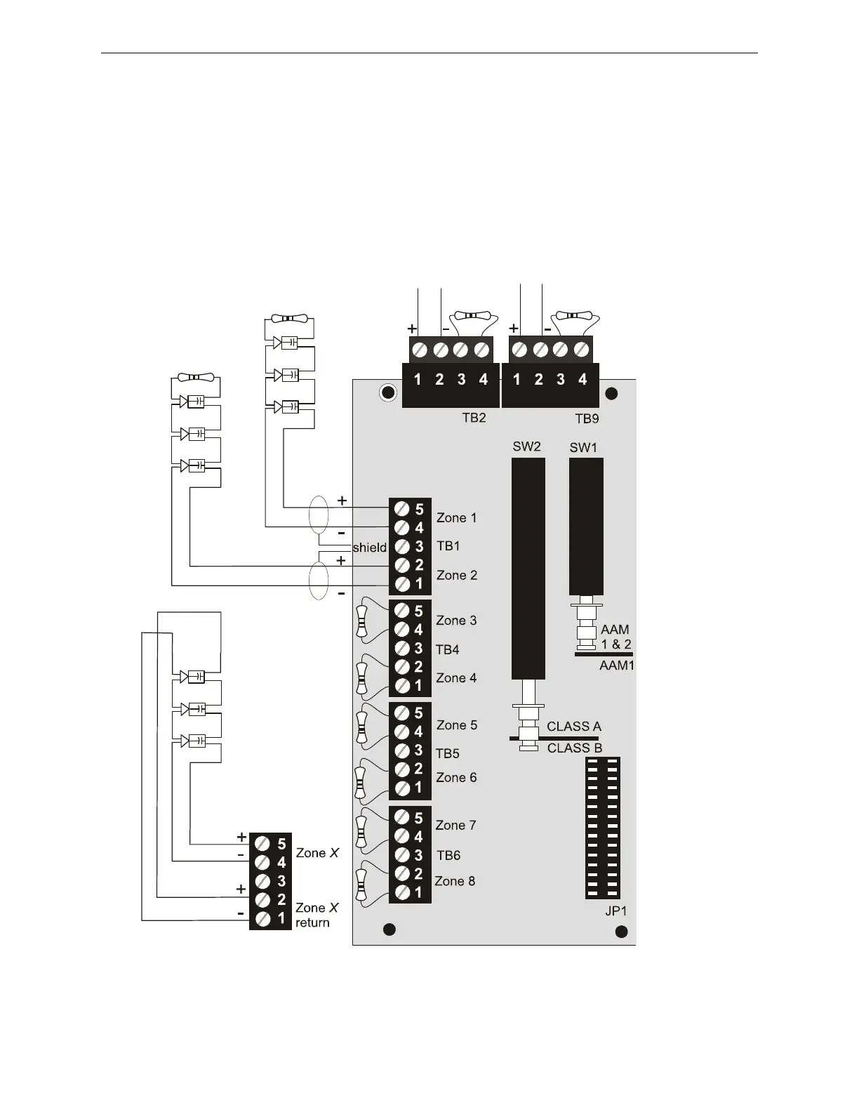
The ACC-ZSM Zone Splitter Module provides connections for four Style Z (Class A) or eight
Style Y (Class B) speaker circuits. Circuits are configured by setting switch SW2 on the ACC-
ZSM to the Class A or Class B position (refer to Section “ACC-ZSM Zone Splitter Module
(ACC-25/50ZS & ACC-25/50ZST)” on page 41).
Class A (Style Z) Wiring
Jumper all unused circuits (+ to + and - to -)
when configured for Class A wiring.
Class B (Style Y) Wiring
ELR Resistor required for
Style Y (Class B) only
4.75K, 1 watt, P/N:75470
To TB1 pins 3 & 4 on
ACC-AAM25 #1
To TB1 pins 3 & 4
on ACC-AAM25 #2
Dummy load all unused
circuits with 4.75K, 1
watt resistor, P/N: 27589
when configured for
Class B wiring.
SW1 shown set for
Split Amplifier
operation, where TB1
& TB2 are driven by
ACC-AAM25 #1 and
TB5 & TB6 are driven
by ACC-AAM25 #2.
SW2 shown set
for Class B wiring
4.75K, 1 watt resistor,
P/N: 27589 required
when ACC-AAM25 is
connected to terminals.
a
c
c
z
s
m
w
i
r
e
.
w
m
f
Figure 3.14 Zone Splitter Module
CAUTION! For correct supervision in the split amplifier configuration, ACC-ZSM TB2 pins 1 & 2
must connect to ACC-AAM25 #1 and ACC-ZSM TB9 pins 1 & 2 must connect to ACC-AAM25 #2
a
c
c
z
s
m
w
i
r
e
.
w
m
f