Audio Command Center Series Manual — P/N 51889:E1 6/8/2010 17
Product Features Product Description
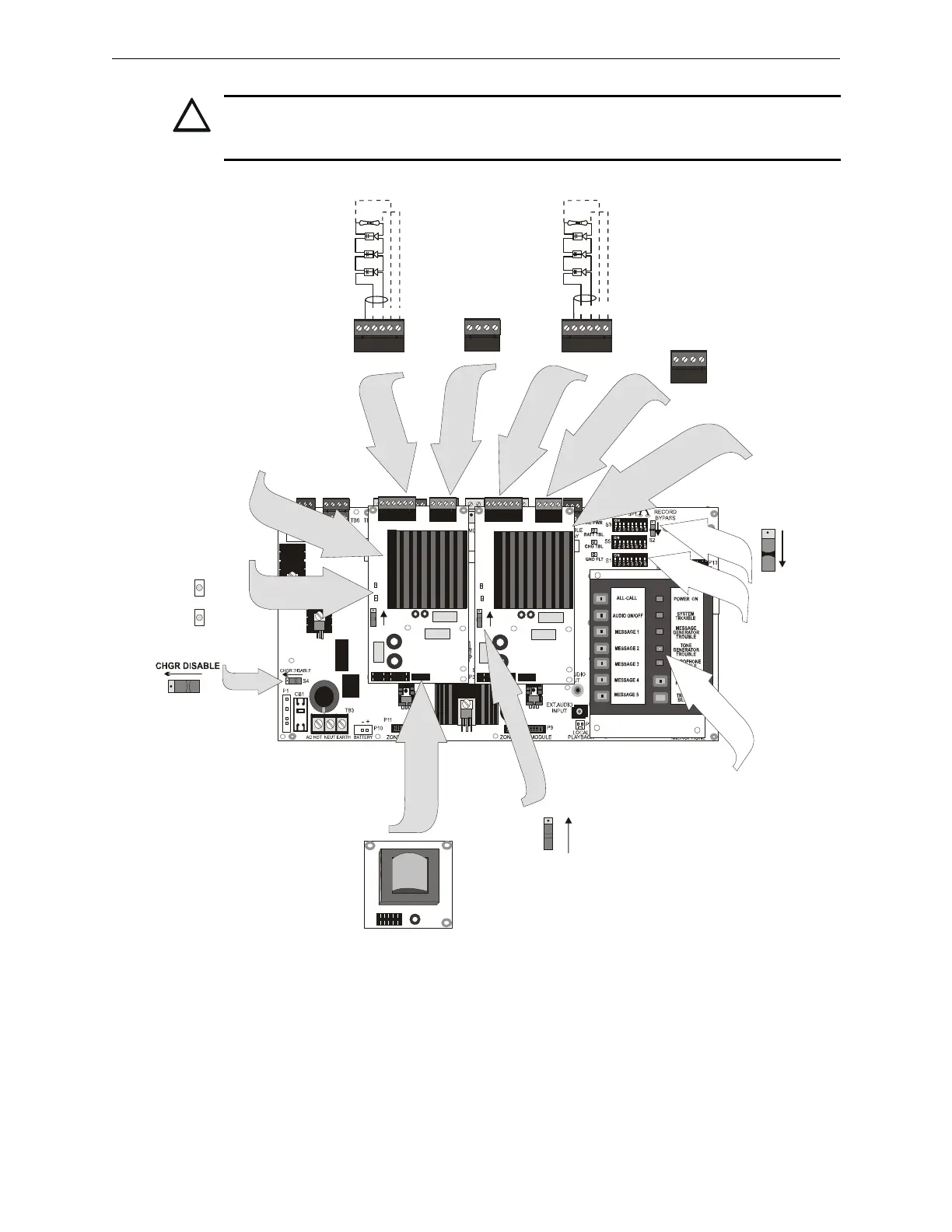
CAUTION: OBSERVE PROPER POLARITY
MATCH PROPER POLARITY CONNECTIONS TO FIELD WIRING AND SPEAKERS. POLARITY
SHOWN IS IN THE STANDBY AND ALARM CONDITIONS.
TB1 TB2
P1
SW1
BACK-UP ON
CKT TBL
AMP SUPV
J1
TB1 TB2
P1
SW1
BACK-UP ON
CKT TBL
AMP SUPV
J1
TB2
1 2 3 4
1 2 3 4
S2
S1
BACK-UP ON
+ - + -
+ - + -
S4
AC25MNT2.wmf
+ - + -
+ - + -
Speaker Circuits are supervised
and power-limited
ELR Resistor required only for
Style Y (Class B) circuits.
4.75 K, 1 watt P/N: 75470
Figure 1.2 Command Board With Amplifiers
Backup Audio
In Out
Backup Audio
In Out
Optional 2nd or
Backup Amplifier
ACC-AAM25
Field
Programmable
Option Switches
S3, S5, and S1
Controls and
System Status
Indicators
(Switch S1 of 2nd amplifier
shown in Backup ‘OFF’ condition
FC-XRM70
Optional 70.7 VRMS Plug-in
Conversion Module
(available for each amplifier)
Battery Charger
Disable Switch
(switch shown for
charger enabled)
LEDs on each amplifer
Amp
Supervision
Circuit
Trouble
Standard
Main Amplifier #1
ACC-AAM25