Audio Command Center Series Manual — P/N 51889:E1 6/8/2010 21
Specifications Product Description
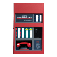
ACC-ZSM Zone Splitter Module and ACC-ZPMK Zone Page Module (ACC-25/50ZS/T
Only)
Power-limited circuitry
Operation: Circuits on ACC-ZSM can be wired as eight Style Y or four Style Z
Normal Operating Voltage for Speaker Circuits: 25 V
RMS
@ 1 amp max. and maximum Load
Impedance of 25
(70.0 V
RMS
@ 350 mA max. with maximum Load Impedance of 200operation possible by
plugging optional FC-XRM70 conversion module into P1 of audio amplifier).
Speaker circuit wiring is supervised during standby and alarm. (Note that background music is not
permitted in Zone Splitter configuration since open-circuit fault detection is not possible)
Output Power: 25 watts total; Frequency Range: 800Hz - 2,800Hz
Maximum total capacitance for ACC-AAM25: 250 µF. (Note that the total
capacitance for the
ACC-ZSM speaker outputs must not exceed the maximum of 250 µF).
End-of-Line Resistor required for Style Y (Class B) speaker circuit: 4.75 K, 1 watt (P/N: 75470)
TB1 on ACC-ZPMK: ACS (EIA-485) electrically isolated link to FACP provides programmed
speaker control
ACC-FFT Fire Fighter Telephone Module (ACC-25/50ZST Only)
Power-limited circuitry
TB1 Remote Phone Circuit Operation: Circuit can be wired Style Y (Class B) or Style Z (Class A)
Wiring connects Remote Page Jacks (FPJ-F or RPJ-F) to control panel for phone communication
Normal Operating Voltage (V
RMS
): Standby = n/a, Active = 0.2 V
RMS
Normal Operating Voltage (VDC): Standby = 12 VDC, Active = 4 VDC to 0.9 VDC
Normal Operating Current (mA): Standby = 1.3 mA, Active = 5 mA
Circuit wiring is supervised.
Maximum wiring impedance = 54
End-of-Line Resistor required for Style Y circuit: 4.7K, ½ watt
TB2 Remote Page Jack Keyswitch Operation: Circuit wired Class B
Keyswitch enables All-Call Paging by FHS-F Remote Phone
Requires RPJ-F
Circuit wiring is supervised.
Maximum wiring impedance = 54
End-of-Line Resistor required: 4.7K, ½ watt
TB3 Remote Microphone Operation:
Provide connection for the optional FC-RM Remote Microphone Module which is used for remote
paging capabilities.
Master CMD Out - TB6 Terminals 1(+), 2(+), 3(-) & 4(-) (active polarity shown)
Provides All-Call Paging trigger for Distributed Audio units (ACC-25/50 ONLY). Will drive MR-
101C or MR-201C relays (manufactured by Air Products and Controls) to provide relay contacts.
Supervised and power-limited circuitry
Programmed Operation: Output reverses polarity on activation of All-Call switch, Remote Micro-
phone or External Page Module input.
Normal Operating Voltage: 24 VDC regulated, filtered; Maximum Voltage: 25.4 VDC
Reverse Polarity Current: 125 mA maximum.
Standby Voltage: -5 VDC. Short Circuit Current: 0.5 mA. Maximum Load Resistance: 200 ohms.
Wiring connections to Master CMD Output Circuit:
NOTE: For installations that require both the Fire Fighter Telephone and Remote Microphone,
the Remote Microphone Module wiring connections are made to the ACC-FFT Fire Fighter
Telephone Module.