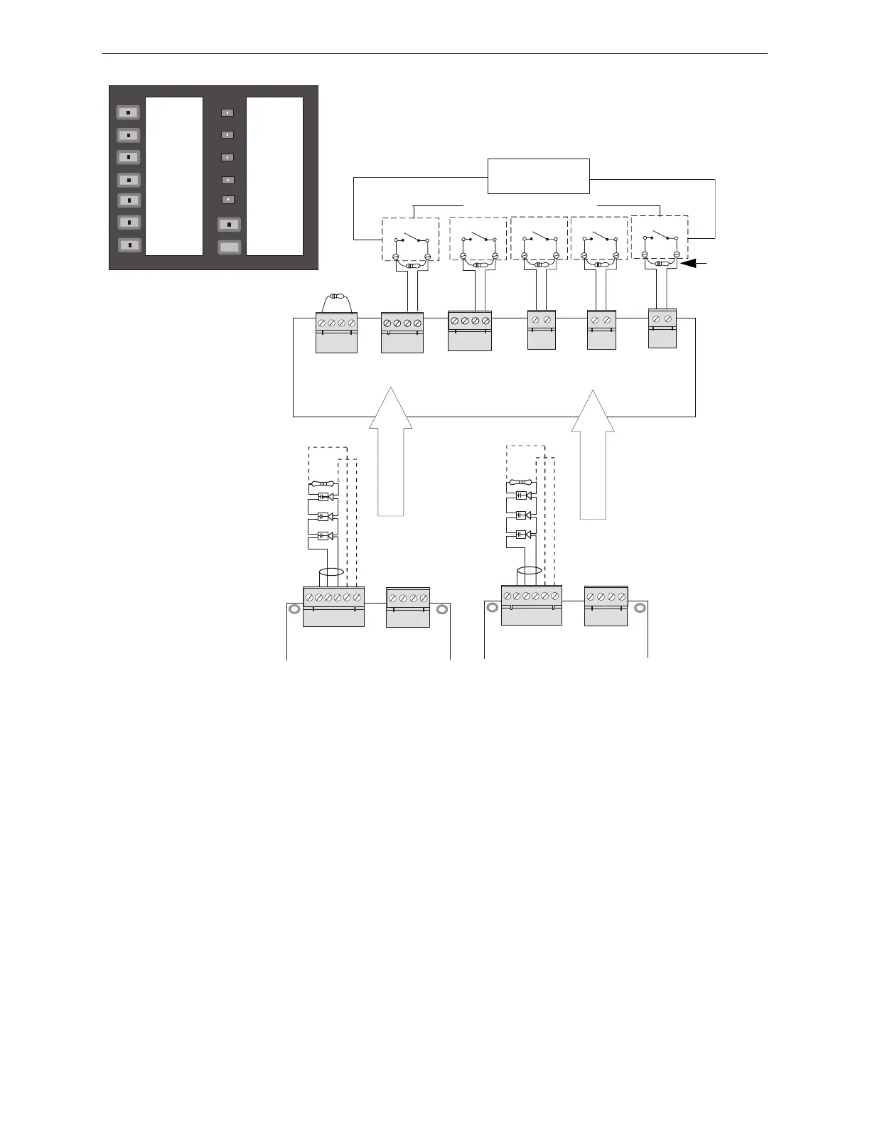
Figure 5.4 Two Speaker Circuits - Single Output Zone, Five Input Channels (five messages)
SLC Loop
ACC-25/50 Series
Main Circuit Board
Style Z
Style Z
Supervisory
Polarity Shown
Supervisory
Polarity Shown
a
c
2
5
a
p
p
1
.
w
m
f
*ELR Resistor required only
for Style Y - Class B
4.75K, 1 watt P/N:75470
*
*
Note: Typical illustration of an addressable Fire•Lite control panel and individual
addressable control modules or a control multimodule. Refer to the Command Input
Specification in Section 1.2, ”Specifications” on page 19, for the voltage range.
SLC Loop
4.7K
ELRs
(P/N: 27072)
Addressable FACP
Addressable Control Modules
or single multimodule
First Amplifier
Mounted on Main Circuit Board
Second Amplifier
Mounted on Main Circuit Board
+ -
+ -
+ -
Keypad Example
4.7K ELR
Alarm Polarities Shown
a
c
c
2
5
k
y
b
l
n
k
.
w
m
f
ALL-CALL
AUDIO ON/OFF
FIRE
MESSAGE
FIRE ALERT
MESSAGE
TORNADO
MESSAGE
CHEM SPILL
MESSAGE
ALL CLEAR
MESSAGE
POWER ON
SYSTEM
TROUBLE
MESSAGE
TROUBLE
GENERATOR
TONE
GENERATOR
TROUBLE
RECORD
PLAYBACK
TROUBLE
SILENCE
MICROPHONE
TROUBLE