– 12 –
Installing the Control's Circuit Board Alone, or (if used), with a 4204, 4219
or 4229 Module
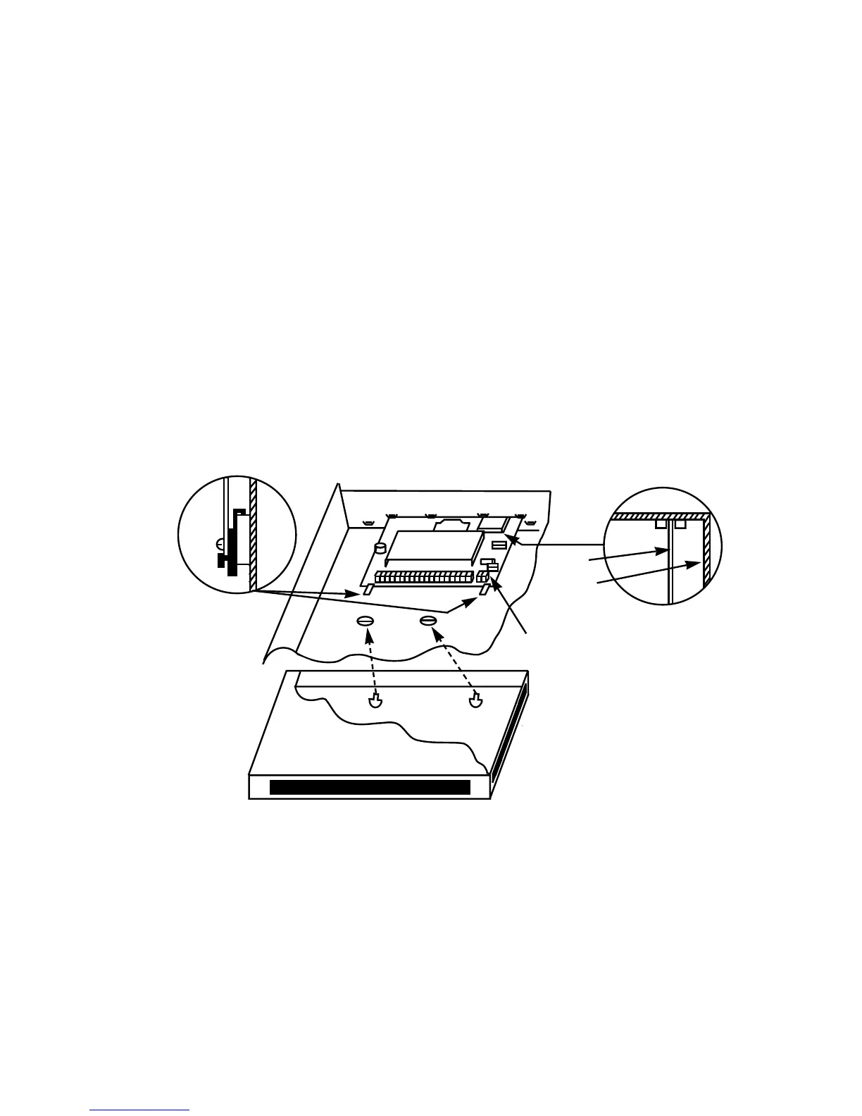
Installing the Control's Circuit Board in the Cabinet
1. Hang two
long Red
mounting clips (provided) on the raised cabinet tabs
(see Detail B in Fig. 2).
2. Insert the top of the circuit board into the slots at the top of the cabinet.
Make sure that the board rests on the correct row (see Detail A in Fig. 2).
3. Swing the base of the board into the mounting clips and secure the board
to the cabinet with the accompanying screws (see Detail B in Fig. 2).
Installing the 4204, 4219 or 4229 Module in the Cabinet
Any one of these units can be mounted in the cabinet with the main control
board, if used. See Figure 2.
1. Insert self-tapping screws (provided) in two adjacent raised cabinet tabs.
Leave the heads projecting 1/8".
2. Hang the unit on the screw heads via two of the slotted holes at the rear of
its housing, as shown in Figure 2.
3. The 4204's cover can be left off if the unit's DIP switch is set with its
position 1 "ON" (to the right) as shown in its instructions. The 4219's or
4229's cover can be left off if the cover tamper jumper is placed in its up-
per (not tampered) position (see Detail C).
The tampered cover is necessary for installations outside of the control's
cabinet.
TAMPERE
NOT
TAMPERED
DETAIL C
4219/4229
COVER TAMPER
JUMPER
DETAIL A
SIDE VIEW OF
BOARD SUPPORTING SLOTS
CIRCUIT
BOARD
CABINET
DETAIL B
SIDE VIEW OF
LONG MOUNTING CLIPS
CONTROL
CIRCUIT
BOARD
Figure 2.
Installing the PC Board in the Cabinet Alone, or (if used), with a 4204, 4219, or 4229
Installing the Control and RF Receiver Circuit Boards Together in the Cabinet
1. Hang two
short
(black) mounting clips (provided with receiver) on the
raised cabinet tabs, as shown in Detail B in Figure 3.
2. Insert the top of the receiver board (removed from its own case as de-
scribed in its instructions) into the slots at the top of the cabinet, as shown
in Detail A in Figure 3. Make sure that the board rests on the correct row of
tabs, as shown.
3. Swing the base of the board into the mounting clips and secure it to the
cabinet with the accompanying screws (see Detail B in Fig. 3).