– 14 –
Standard Phone Line Connections
The wiring connections shown here are not applicable if the FA4285 Phone
Module is used. Refer to the FA4285 Phone Module section for information
regarding phone line connections, which are different than those shown here.
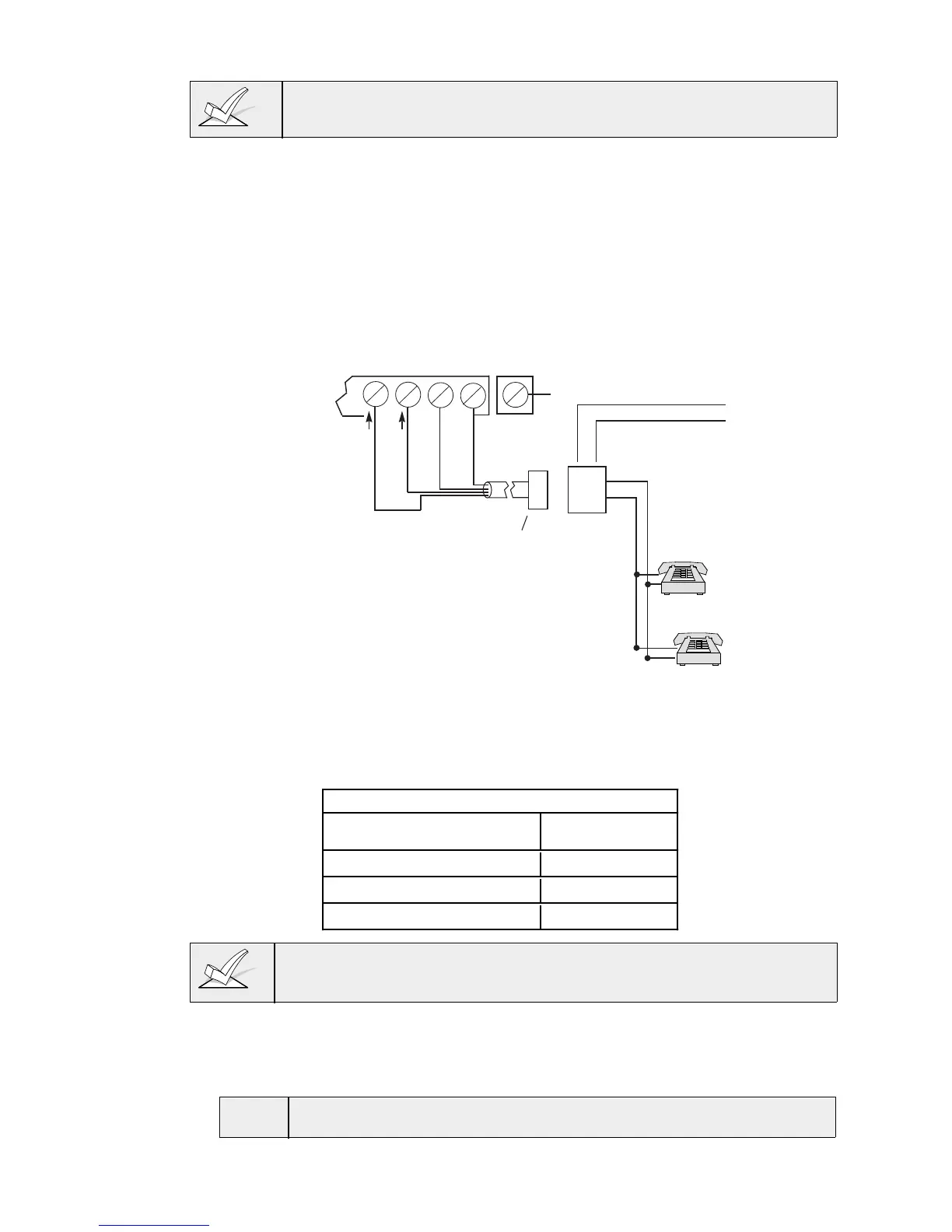
Incoming phone line and handset wiring is connected to the main terminal
block via a RJ31X jack (CA38A jack in Canada), as indicated below and
shown in Figure 4.
Term. 17: Local Handset (TIP – Brown*).
Term. 18: Local Handset (RING – Gray*).
Term. 19: Incoming Phone Line (TIP – Green*).
Term. 20: Incoming Phone Line (RING – Red*).
* Colors of wires in Direct Connect Cord.
TERMINALS
ON CONTROL
EARTH GROUND
➡
PREMISES
PHONES
Handset
Incoming
Telco Line
TIP
RING
BROWN (TIP)
GRAY (RING)
GREEN (TIP)
RED (RING)
RJ31X
JACK
PLUG
DIRECT
CONNECT
CORD
➧
TIP
RING
GROUND
▲
▲▲
INCOMING TELCO LINE
▲
{
{
17 18 19 20 21
CA38A
JACK IN
CANADA
Figure 4. Standard Telephone Line Connections
Wiring The AC Transformer
1321 Transformer
(1321CN in Canada)
Wire the transformer to terminals 1 and 2 on the control board. See the wiring
table below for wire gauge to use.
WIRING TABLE
Distance of Transformer Wire Gauge
From the Control Panel To Use
Up to 50 feet # 20
50–100 feet # 18
100–250 feet # 16
Wiring to the AC Transformer must not exceed 250 feet using 16 gauge wire.
Do not plug the transformer into the AC outlet until you are instructed to do so
later in the manual.
Installing The Back-Up Battery
1. Place the 12-volt back-up battery in the control cabinet. To calculate the
correct battery size for an installation, refer temporarily to “Calculating the
Battery Size Needed” in the
FINAL POWER UP
section.
U
L
Use a 4AH battery or larger for UL installations.