– 11 –
Section 2. INSTALLING THE CONTROL
This section provides instructions for mounting the control cabinet, and
installing the cabinet lock (if used). Also included in this section are instructions
for the following:
• Installing the main PC board.
• If used, optional mounting one of the following in the cabinet with the main
PC board: RF Receiver board, 4204 Relay unit, 4219 Wired Expansion
unit, or 4229 Wired Expansion/Relay unit.
• Standard phone line connections.
• Installing the back-up battery in the cabinet.
• Connecting the AC transformer.
• Making earth ground connections.
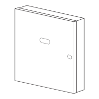
Mounting the Cabinet
Mount the control cabinet to a sturdy wall using fasteners or anchors (not
supplied), in a clean, dry area which is not readily accessible to the general
public. Four mounting holes are provided at the back of the cabinet.
If an RF Receiver is being used and you intend to mount its PC board within
the cabinet, note the following:
• Do not mount the cabinet on or near metal objects. This will decrease RF
range and/or block RF transmissions from wireless transmitters.
• Do not locate the cabinet in an area of high RF interference (revealed by
frequent or prolonged lighting of the LED in the receiver after it is
operational). Random flicker is OK.
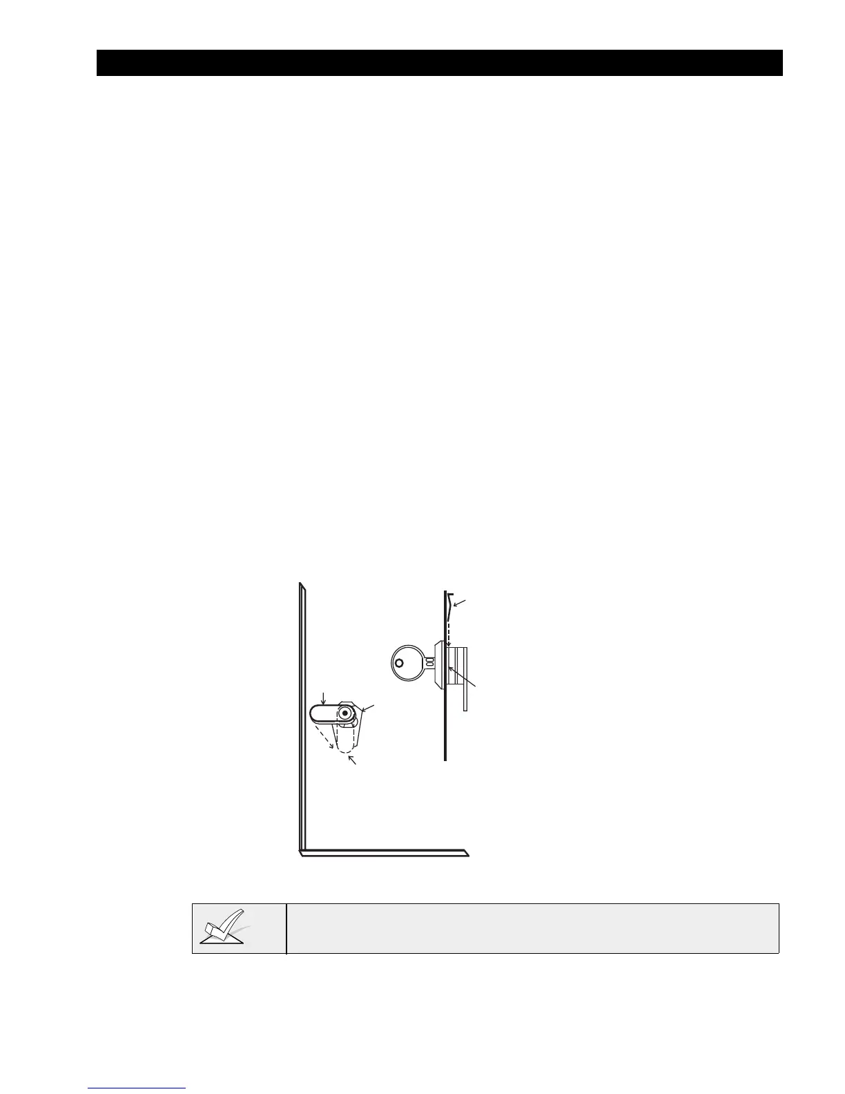
Installing the Lock (if used)
Use an Ademco No. N6277 Cam Lock and No. N6277–1 Push-On Clip
(Retainer Clip).
Note: The cabinet can be closed and secured
without
a lock by using 2
screws in the cover's edge.
CABINET DOOR BOTTOM
RETAINER
CLIP
RETAINER CLIP
(NOTE POSITION)
RETAINER
SLOTS
LOCKED
UNLOCKED
Figure 1. Installing the Lock
1. Remove the cabinet door.
It is easily removable for
servicing and is easily re-
installed.
2. Remove the lock knockout
from the control cabinet
door. Insert the key into
the lock. Position the lock
in the hole making certain
that the latch will make
contact with the latch
bracket when the door is
closed.
3. Hold the lock steady, and
insert the retainer clip into
the retainer slots. Position
the clip as illustrated in
order to permit easy
removal.
Before installing the cabinet's contents, remove the metal cabinet knock-outs
required for wiring entry. Do not attempt to remove the knockouts after the
circuit board has been installed.