– 25 –
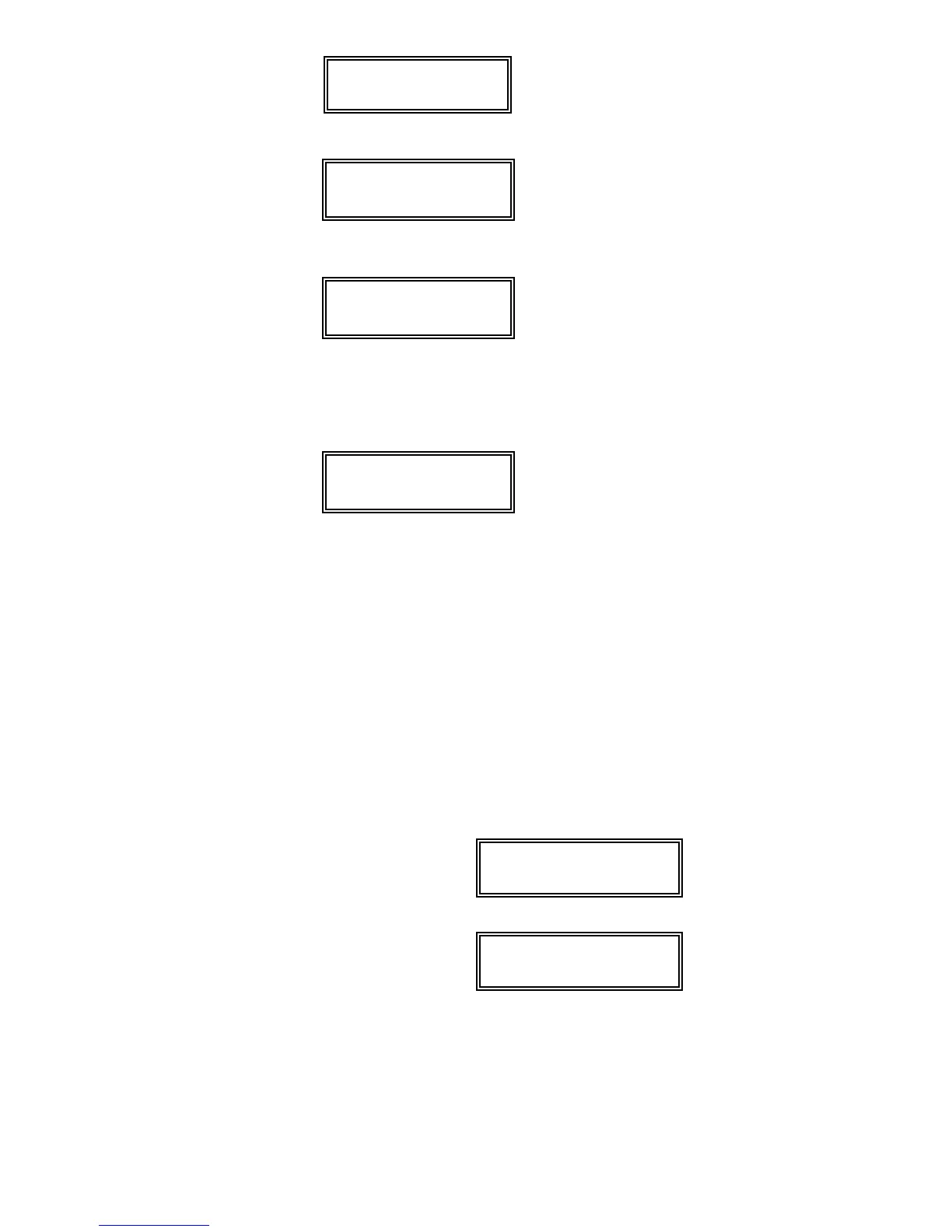
10 Input Dev: LP#
AUX WIRED AW: 01
At the “INPUT DEVICE” prompt, enter “2” (AUX
Wired) as the input device. The display on the
left will appear.
Press [
✱
] to continue.
Typical summary display
Zn ZT RC In L
10 03 – 03 AW: –
A summary display will appear, showing the
data for the zone that was just programmed.
Note that AW indicates an auxiliary wired (zone
expansion module) zone.
If it is programmed satisfactorily, press [
✱
] to
display the next prompt.
Program Alpha?
0 = No 1 = Yes 0
For all zone types, the next request is to enter
Alpha descriptors for the zones. The entry may
be done now (enter 1) or may be done at a later
time using
✱
82 interactive menu mode (enter 0).
We recommend that the entry of Alpha
descriptors be done later using
✱
82 menu
mode.
See
ALPHA DESCRIPTION PROGRAMMING
section for specific procedure.
Enter Zn Num.
(00 = Quit) 11
Enter next zone number ↑
If “0” (No) was entered above, the system will
display a prompt for entry of the next wired
expansion zone number. Proceed with the
programming for the next zone, as indicated
previously.
When all wired expansion zones are
programmed satisfactorily, exit
✱
56 mode at the
Enter Zn Num. prompt by pressing: [0] [0]
✱
.
Exit the programming mode by keying
✱
99.
Proceed to the check-out procedure that follows.
Check-Out Procedure For Wired Expansion Zones
After you have completed installation of all devices, all wired expansion zones
should be checked as follows:
1. Make certain that all devices and sensors connected to the wired expansion
zones are not in a faulted state. Doors and windows with contacts should be
closed, PIRs should be covered (use a cloth to mask them temporarily if
necessary).
2. With all zones intact (including hard-wired zones), the Alpha keypad
connected to the system should display:
✶✶✶
DISARMED
✶✶✶
READY TO ARM.
If the following is displayed,
DISARMED Press ✱
to show faults
press the [
✱
] key to display the faulted zone(s). Restore any faulted zone(s)
as necessary.
Make sure that you have connected a 1000 ohm EOL resistor across
the terminals of unused expansion zones on the 4219 or 4229 module).
When the READY TO ARM message is displayed, you can proceed to the
next step.
(Continued)