– 16 –
Section 3. INSTALLING REMOTE KEYPADS
This section lists the wired keypads that may be used and provides
instructions for wiring and mounting the keypads.
A preliminary check-out procedure is also provided to ensure that the
connected keypads are functioning properly in the system.
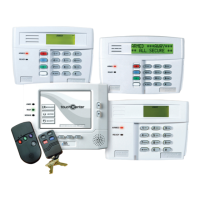
Keypads That May Be Used
• Fixed-Word Display: FA210KP, FA250KP
• Alpha Display: FA550KP
• Up to 4 keypads, independent of auxiliary power considerations (you may
need to use an auxiliary power supply if the 500mA aux. output is
exceeded)
Be sure the keypads are set to the non-addressable mode (address 31).
Wiring To The Keypads
1. Determine wire gauge by referring to the wiring length/gauge chart below.
For devices (Keypads, RF Receivers, Expansion/Relay units, etc.)
connected to a single 4-wire run, determine the current drawn by all units
connected to the single wire run, then refer to the Wiring Run chart to
determine the maximum wire length that can be safely used for each wire
size. Current draw for all devices can be found in the
SPECIFICATIONS
AND ACCESSORIES
section.
Note: Refer to “Auxiliary Device Current Draw Worksheet” in the
FINAL
POWER UP
section for current draw for all keypads.
Maximum wire lengths for any device that is homerun to the control can also
be determined from the chart, based on the current draw of that device alone.
Wiring Run Chart For Devices* Drawing Aux Power From The Control (12V+ & 12V–)
TOTAL CURRENT DRAWN BY ALL DEVICES CONNECTED TO A SINGLE WIRE RUN
Wire Size 50mA or less 100mA 300mA 500mA
#22 500 ft (152m) 250 ft (76m) 80 ft (24m) 50 ft (15m)
#20 750 ft (228.6m) 380 ft (116m) 130 ft (39.6m) 80 ft (24m)
#18 1300 ft (396m) 650 ft (198m) 220 ft (67m) 130 ft (39.6m)
#16 1500 ft (457m) 1000 ft (305m) 330 ft (100.5m) 200 ft (70m)
* Includes Keypads, RF Receivers, Expansion/ Relay Units, or the FA4285 Phone Module.
The length of all wire runs must not exceed 1500 feet (457m) when
unshielded quad conductor cable is used (750 feet if shielded cable is used).
This restriction is due to the capacitive effect
on the data lines
when quad
cable is used.
2. Run field wiring from the control to the keypads (using standard 4-
conductor twisted wire cable using the wire gauge determined in step 1).
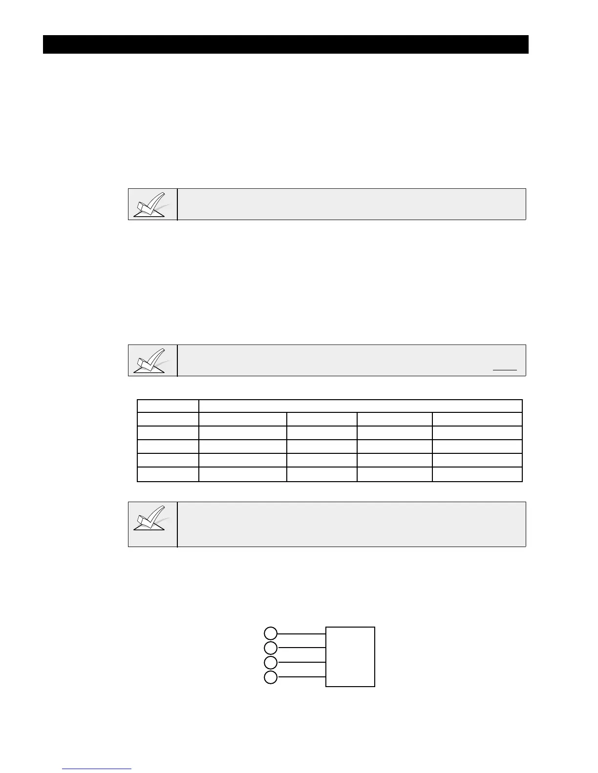
3. Connect remote Keypads to terminals 4, 5, 6, and 7 on the control board.
KEYPADS
BLACK
RED
GREEN
YELLOW
4
5
6
7
CONTROL
TERMINALS
KEYPAD CONNECTOR CABLE
↓
Figure 5. Keypad Connections To The Control Board