ACCESSORIES
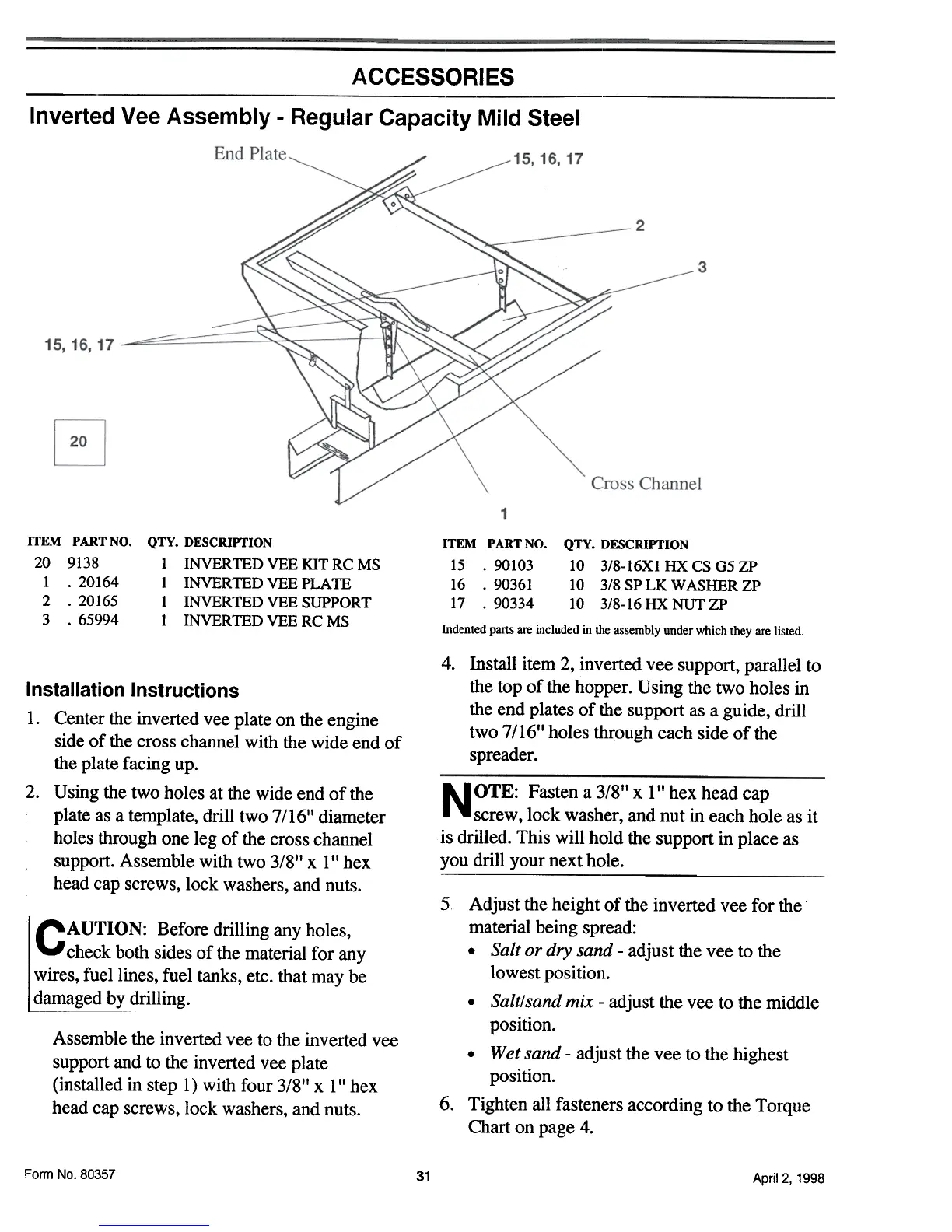
Inverted Vee Assembly -Regular Capacity Mild Steel
ITEM PART NO.
20 9138
1 .20164
2 .20165
3 .65994
QTY. DESCRIYfION
1 INVERTED VEE KIT RC MS
1 INVERTEDVEEPLATE
1 INVERTED VEE SUPPORT
1 INVERTED VEE RC MS
ITEM PART NO. QTY. DESCRIPTION
15 .90103 10 3/8-16X1 HX CS 05 ZP
16 .90361 10 3/8 SP LK WASHER ZP
17 .90334 10 3/8-16 HX NUT ZP
Indented parts are included in the assembly under which they are listed.
4. Install item 2, inverted vee support, parallel to
the top of the hopper. U sing the two holes in
the end plates of the support as a guide, drill
two 7/1611 holes through each side of the
spreader.
Installation Instructions
1. Center the inverted vee plate on the engine
side of the cross channel with the wide end of
the plate facing up.
2. U sing the two holes at the wide end of the
plate as a template, drill two 7/161' diameter
holes through one leg of the cross channel
support. Assemble with two 3/8" x 1 " hex
head cap screws, lock washers, and nuts.
NOTE: Fasten a 318'1 x 1" hex head cap
screw, lock washer, and nut in each hole as it
is drilled. This will hold the support in place as
you drill your next hole.
5
l§~~!AUTION: Before drilling any holes,
check both sides of the material for any
wires, fuel lines, fuel tanks, etc. tha~ may be
damaged by drilling.
Assemble the inverted vee to the inverted vee
support and to the inverted vee plate
(installed in step I) with four 3/811 x 111 hex
head cap screws, lock washers, and nuts.
6.
Adjust the height of the inverted vee for the
material being spread:
.Salt or dry sand -adjust the vee to the
lowest position.
.Salt/sand mix -adjust the vee to the middle
position.
.Wet sand -adjust the vee to the highest
position.
Tighten all fasteners according to the Torque
Chart on page 4.
Form No.80357
31
April 2, 1998