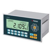
FT-112(D) Panel Weighing Indicator, Technical Manual, Rev.1.0.0, May 2019 Page 9 of 170
Max. load resistance
(current output)
Minimum load resistance
(voltage output)
Up to 12000 kbit/s with automatic baud rate detection
Generic GSD-file provided
Depending on physical media
RS-485: segmented line topology without stubs
Shielded twisted pair cable
Line length depending on physical media and transmission speed
up to 126 stations per network
Galvanically isolated bus electronics
Min. 4 ms response delay after read/write commands
Digital inputs and outputs of the instrument can be programmed independently as
a Remote IO’s of PLC to control them over fieldbus.
Generic GSDML-file provided
DHCP or manual IP are assigned over Indface2x PC Software or by keys in
programming mode. Device identity customization
Line, Bus, Star or Tree topology depending on physical media
Switched Ethernet transmission with shielded twisted pair cables and RJ-45
connectors.
Galvanically isolated bus electronics
Min. 4 ms response delay after read/write commands
Digital inputs and outputs of the instrument can be programmed independently as
a Remote IO’s of PLC to control them over fieldbus.
10 kbit/s – 1 Mbit/s (selectable) kbit/s
Generic EDS-file provided
Line with Trunkline, Dropline structure and Termination at both Ends
Line length depending on baud rate 25 – 500 meters.
2 wire shielded twisted pair cable
Alternatively, 4 wire with 24 Volt power over the bus
Up to 127 stations per network
Galvanically isolated bus electronics
Min. 4 ms response delay after read/write commands
Digital inputs and outputs of the instrument can be programmed independently as
a Remote IO’s of PLC to control them over fieldbus.