3.7Generallocationrequirements
Importantconsiderationswhenchoosingasuitable
locationforyourproduct.
Thisproductissuitableformountingbelowdecks.
Theproductshouldbemountedwhereitwillbe:
•protectedfromphysicaldamageandexcessive
vibration.
•wellventilatedandawayfromheatsources.
Whenchoosingalocationfortheproduct,
considerthefollowingpointstoensurereliableand
trouble-freeoperation:
•Access—theremustbesufcientspaceto
enablecableconnectionstotheproduct,avoiding
tightbendsinthecable.
•Diagnostics—theproductmustbemountedin
alocationwherethediagnosticsLEDiseasily
visible.
Note:Notallproductsincludeadiagnostics
LED.RefertotheChapter8Systemchecks
andtroubleshootingformoreinformation.
•Electricalinterference—theproductshouldbe
mountedfarenoughawayfromanyequipment
thatmaycauseinterferencesuchasmotors,
generatorsandradiotransmitters/receivers.
•Magneticcompass—refertotheCompass
safedistancesectioninthisdocumentforadvice
onmaintainingasuitabledistancebetweenthis
productandanycompassesonyourvessel.
•Power—tokeepcablerunstoaminimum,the
productmustbelocatedascloseaspossibleto
thevessel’sdcpowersupply.
•Mountingsurface—ensuretheproductis
adequatelysupportedonasecuresurface.Refer
totheweightinformationprovidedintheTechnical
specicationforthisproductandensurethatthe
intendedmountingsurfaceissuitableforbearing
theproductweight.DoNOTmountunitsorcut
holesinplaceswhichmaydamagethestructure
ofthevessel.
Compasssafedistance
Topreventpotentialinterferencewiththevessel's
magneticcompasses,ensureanadequatedistance
ismaintainedfromtheproduct.
Whenchoosingasuitablelocationfortheproduct
youshouldaimtomaintainthemaximumpossible
distancefromanycompasses.Typicallythisdistance
shouldbeatleast1m(3ft)inalldirections.However
forsomesmallervesselsitmaynotbepossibleto
locatetheproductthisfarawayfromacompass.In
thissituation,whenchoosingtheinstallationlocation
foryourproduct,ensurethatthecompassisnot
affectedbytheproductwhenitisinapoweredstate.
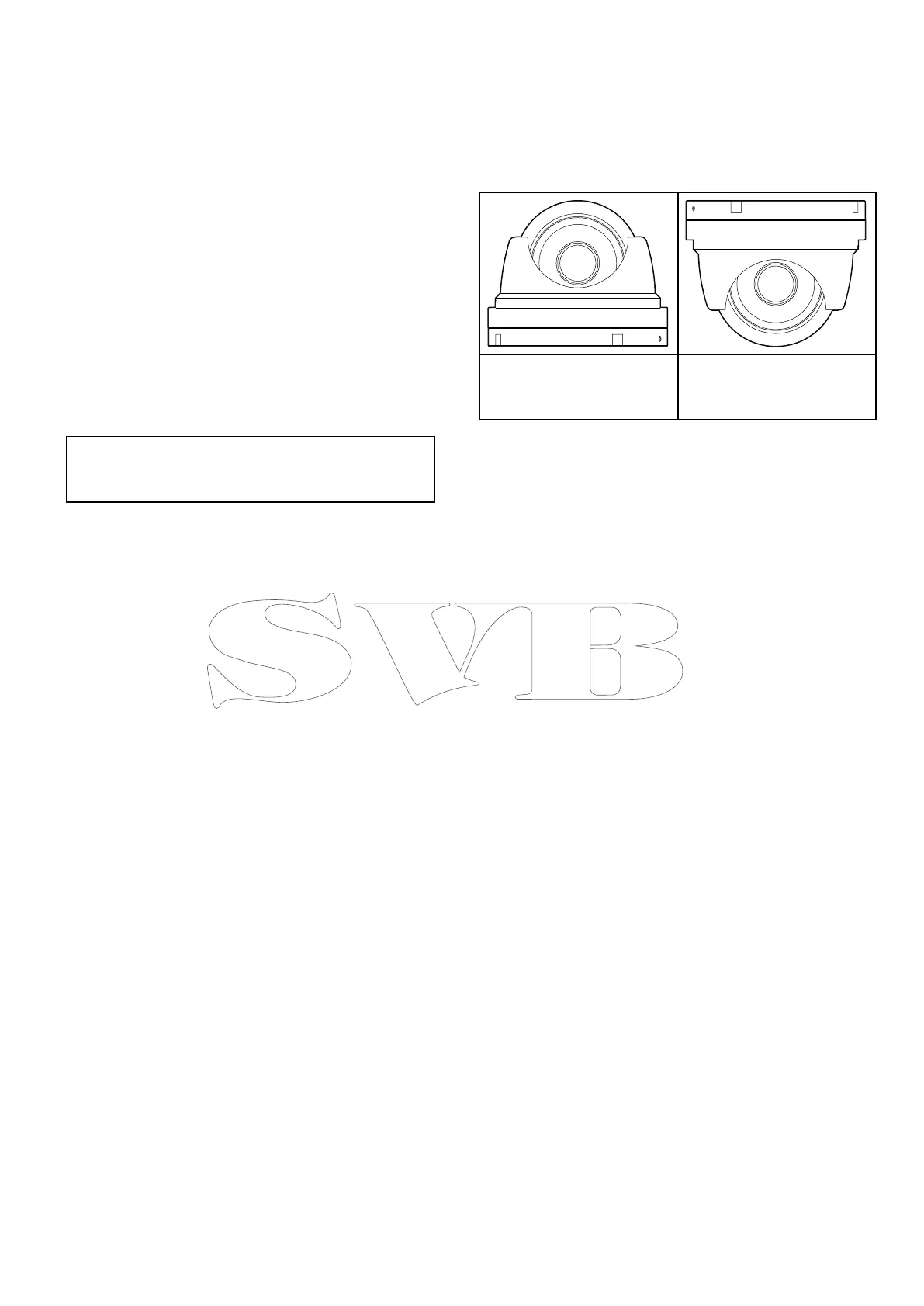
3.8Cameraorientation
Thecameracanbemountedin2orientations
referredtoas“Ballup”and“Balldown”.
Thedefaultimageorientationisfortheball-down
conguration,ifthecameraistobemountedinthe
ball-upcongurationthenthevideoimagemustbe
ipped.
Ball-up:Thecamerais
mountedontopofthe
mountingsurface.
Ball-down:Thecamerais
suspendedupsidedown,
belowthemountingsurface.
Theimageorientationmustbechangedusingthe
built-inwebinterfaceaccessiblewhenconnected
toaPC.
Planningtheinstallation
17
 Loading...