2-wirecablefromtheunittothevessel'sbatteryor
distributionpanel.
•Raymarinerecommendsaminimumwiregauge
of18AWG(0.82mm
2
)foranylengthofcable
extension.
•Foralllengthsofextensiontothepowercable,
ensurethereisacontinuousminimumvoltage
attheproduct’spowerconnectorof10.8Vwitha
fullyatbatteryat11V.
Important:Beawarethatsomeproductsin
yoursystem(suchassonarmodules)cancreate
voltagepeaksatcertaintimes,whichmayimpact
thevoltageavailabletootherproductsduringthe
peaks.
Powerdistribution
Recommendationsandbestpractice.
•Theproductissuppliedwithapowercable.Only
usethepowercablesuppliedwiththeproduct.Do
NOTuseapowercabledesignedfor,orsupplied
with,adifferentproduct.
•RefertothePowerconnectionsectionformore
informationonhowtoidentifythewiresinyour
product’spowercable,andwheretoconnectthem.
•Seebelowformoreinformationonimplementation
forsomecommonpowerdistributionscenarios.
Important:Whenplanningandwiring,takeinto
considerationotherproductsinyoursystem,some
ofwhich(e.g.sonarmodules)mayplacelarge
powerdemandpeaksonthevessel’selectrical
system.
Note:Theinformationprovidedbelowisfor
guidanceonly,tohelpprotectyourproduct.It
coverscommonvesselpowerarrangements,but
doesNOTcovereveryscenario.Ifyouareunsure
howtoprovidethecorrectlevelofprotection,
pleaseconsultanauthorizedRaymarinedealeror
asuitablyqualiedprofessionalmarineelectrician.
Implementation—directconnectiontobattery
•Thepowercablesuppliedwithyourproductmay
beconnecteddirectlytothevessel'sbattery,viaa
suitablyratedfuseorbreaker.
•Thepowercablesuppliedwithyourproductmay
NOTincludeaseparatedrainwire.Ifthisisthe
case,onlythepowercable’sredandblackwires
needtobeconnected.
•IfthesuppliedpowercableisNOTttedwithan
inlinefuse,youMUSTtasuitablyratedfuseor
breakerbetweentheredwireandthebattery’s
positiveterminal.
•Refertotheinlinefuseratingsprovidedinthe
product’sdocumentation.
•Ifyouneedtoextendthelengthofthepowercable
suppliedwithyourproduct,ensureyouobserve
thededicatedPowercableextensionsadvice
providedintheproduct’sdocumentation.
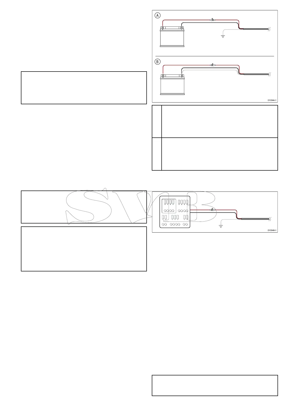
A
BatteryconnectionscenarioA:suitableforavesselwith
acommonRFgroundpoint.Inthisscenario,ifyour
product’spowercableissuppliedwithaseparatedrain
wirethenitshouldbeconnectedtothevessel’scommon
groundpoint.
B
BatteryconnectionscenarioB:suitableforavessel
withoutacommongroundingpoint.Inthiscase,ifyour
product’spowercableissuppliedwithaseparatedrain
wirethenitshouldbeconnecteddirectlytothebattery’s
negativeterminal.
Implementation—connectiontodistribution
panel
•Alternatively,thesuppliedpowercablemaybe
connectedtoasuitablebreakerorswitchonthe
vessel'sdistributionpanelorfactory-ttedpower
distributionpoint.
•Thedistributionpointshouldbefedfromthe
vessel’sprimarypowersourceby8AWG
(8.36mm
2
)cable.
•Ideally,allequipmentshouldbewiredtoindividual
suitably-ratedthermalbreakersorfuses,with
appropriatecircuitprotection.Wherethisisnot
possibleandmorethan1itemofequipment
sharesabreaker,useindividualin-linefuses
foreachpowercircuittoprovidethenecessary
protection.
•Inallcases,observetherecommended
breaker/fuseratingsprovidedintheproduct’s
documentation.
•Ifyouneedtoextendthelengthofthepowercable
suppliedwithyourproduct,ensureyouobserve
thededicatedPowercableextensionsadvice
providedintheproduct’sdocumentation.
Important:Beawarethatthesuitablefuserating
forthethermalbreakerorfuseisdependentonthe
numberofdevicesyouareconnecting.
Cablesandconnections23

 Loading...