21
HARDWARE SETUP MENU
PATCH MANUAL
HARDWARE SETUP MENU
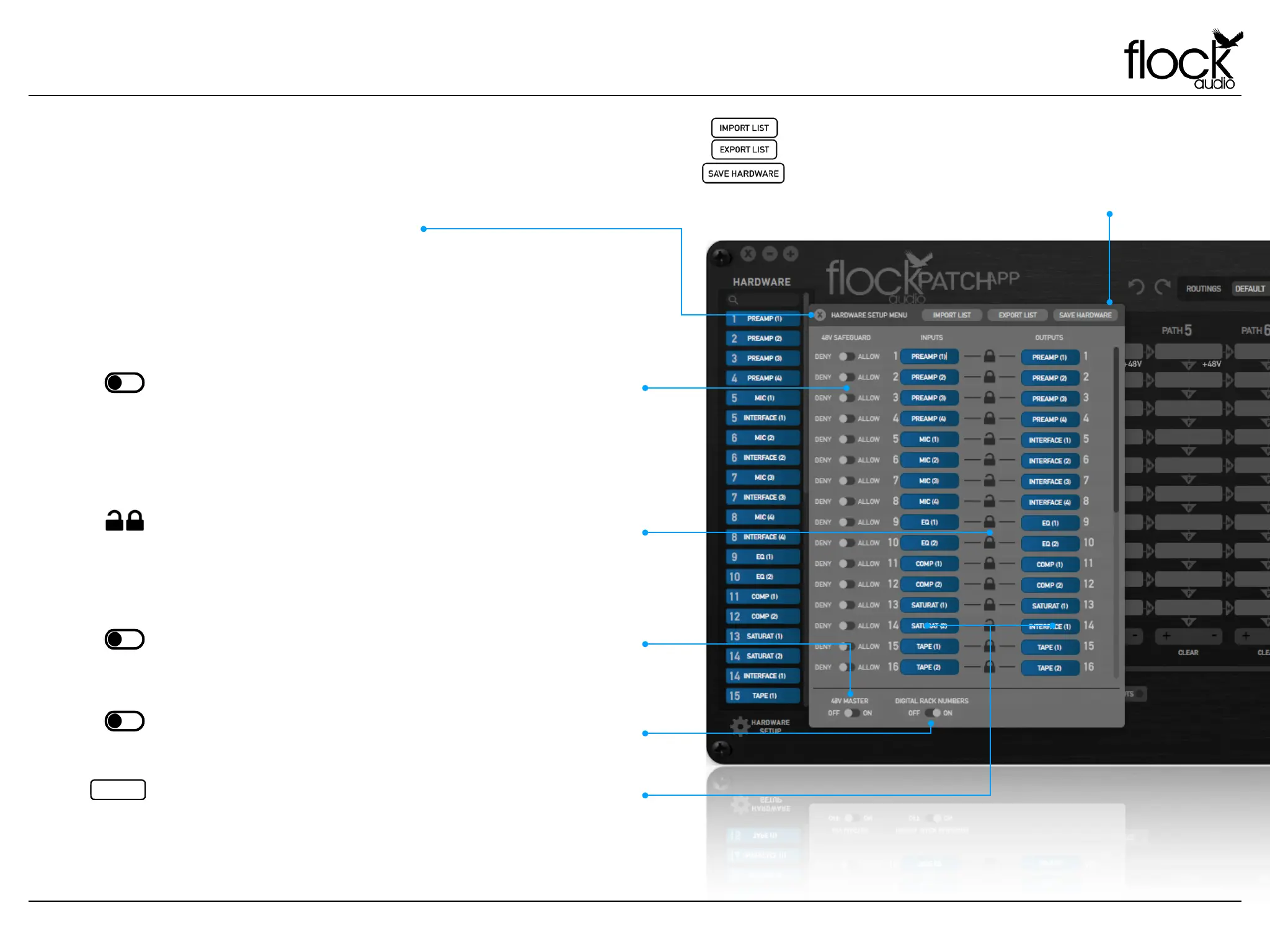
Hardware Setup Menu Overview
The Hardware Setup Menu is where all of the physically connected
analog audio equipment is organized by the user. The Hardware
Setup Menu provides personal preferences for each Input &
Output allowing the user to customize the specific digital rack
spaces according to their needs.
HARDWARE SETUP MENU
Deny / Allow - Each Input on the PATCH Hardware is protected with a Safeguard
Switch that prevents accidental 48V Phantom Power engagements on incompatible
external audio equipment. By default the PATCH APP Deny’s all connected external
audio equipment from having 48V Phantom Power. In order to use 48V you must select
“Allow” which will grant permission for the user to engage 48V Phantom Power on this
Input connection. Note: This switch does not turn on 48V it only allows the user to turn
on 48V with-in the Active Routings Section of the application.
48V Master - The 48V capability for the entire PATCH System can be turned off with
the use of the 48V Master Toggle Switch. When “Off” is selected, 48V will not be
possible to engage on the entire system. When “On” is selected by default, the
System will be able to provide 48V Phantom Power to any granted permission Input.
Digital Rack Numbers - This toggle allows a user to remove the Digital Rack Numbers
embedded on the left side of each digital rack space. This toggle is a visual user
preference only and does not affect the connections of the PATCH Hardware.
Unlink / Link - The Lock icon allows the user to link both the Input & Output of a
corresponding channel together to display only 1 - Digital Rack Space in the Hardware
Index or Unlink the channels to display 2 - Digital Rack Spaces for separate routing
configurations. When “Unlinked” the 2 - Digital Rack Spaces will show in the Hardware
Index, by default the Top corresponding numbered rack will represent the Input and
the Bottom corresponding numbered rack will represent the Output.
Input/Output Text Label - Each Input and Output connection on the PATCH System
Hardware is represented by a Text Label Field in the Hardware Setup Menu. Users can
easily label and revise audio equipment names by simply opening the Hardware Setup
Menu. Note: Always choose “Save Hardware” to store Labels.
Import/Export/Save Hardware - The PATCH APP has the ability to Import &/or
Export existing Hardware lists. When travelling to other recording studios that
use a PATCH System, an engineer can export the existing hardware list from the
chosen studio and send it to the travelling audio engineer user allowing the
user to import the list and review available analog audio equipment while
creating various routings before arriving at the studio.