8
REAR PANEL INDENTIFICATIONS
PATCH MANUAL
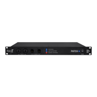
REAR PANEL
24VDC Power Connection!
6 Pin Connector with
threaded locking sleeve
Rear Inputs 1-32!
DB-25/D-SUB Connectors!
Inputs: 1-8, 9-16, 17-24, 25-32
(8 Balanced Audio Channels per Connector)
Tascam 25 Pinout Wiring Standard
USB-B Host Connector!
USB-B to USB-A Cable
(USB 2.0 Connection)
Rear Outputs 1-32!
DB-25/D-SUB Connectors!
Outputs: 1-8, 9-16, 17-24, 25-32
(8 Balanced Audio Channels per Connector)
Tascam 25 Pinout Wiring Standard
Inputs & Outputs (31-32)!
Channels 31-32 can be routed to the
Front Panel Inputs & Outputs using the
PATCH APP Software.
REAR INDENTIFICATIONS
IMPORTANT: Always ensure that the Power
Connector is fastened snuggly into the Power
Input of the PATCH System Hardware.
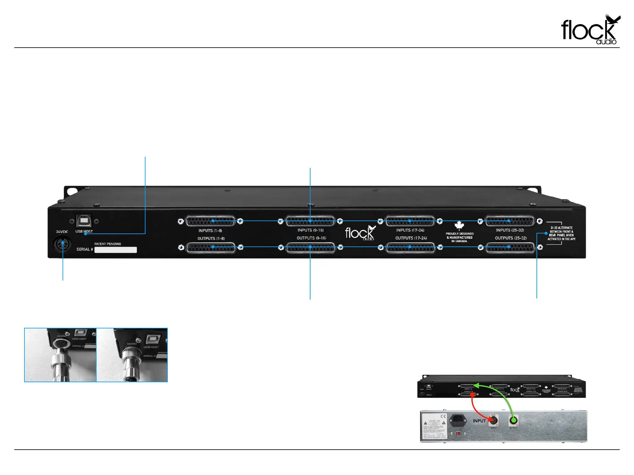
OUTPUT
INPUT
OUTPUTS
INPUTS
(OUTPUT) FROM PATCH TO
(INPUT) OF EXTERNAL GEAR
(OUTPUT) FROM EXTERNAL
GEAR TO (INPUT) OF PATCH