8. Place the end cap vertically on a work bench with
the check valve end up.
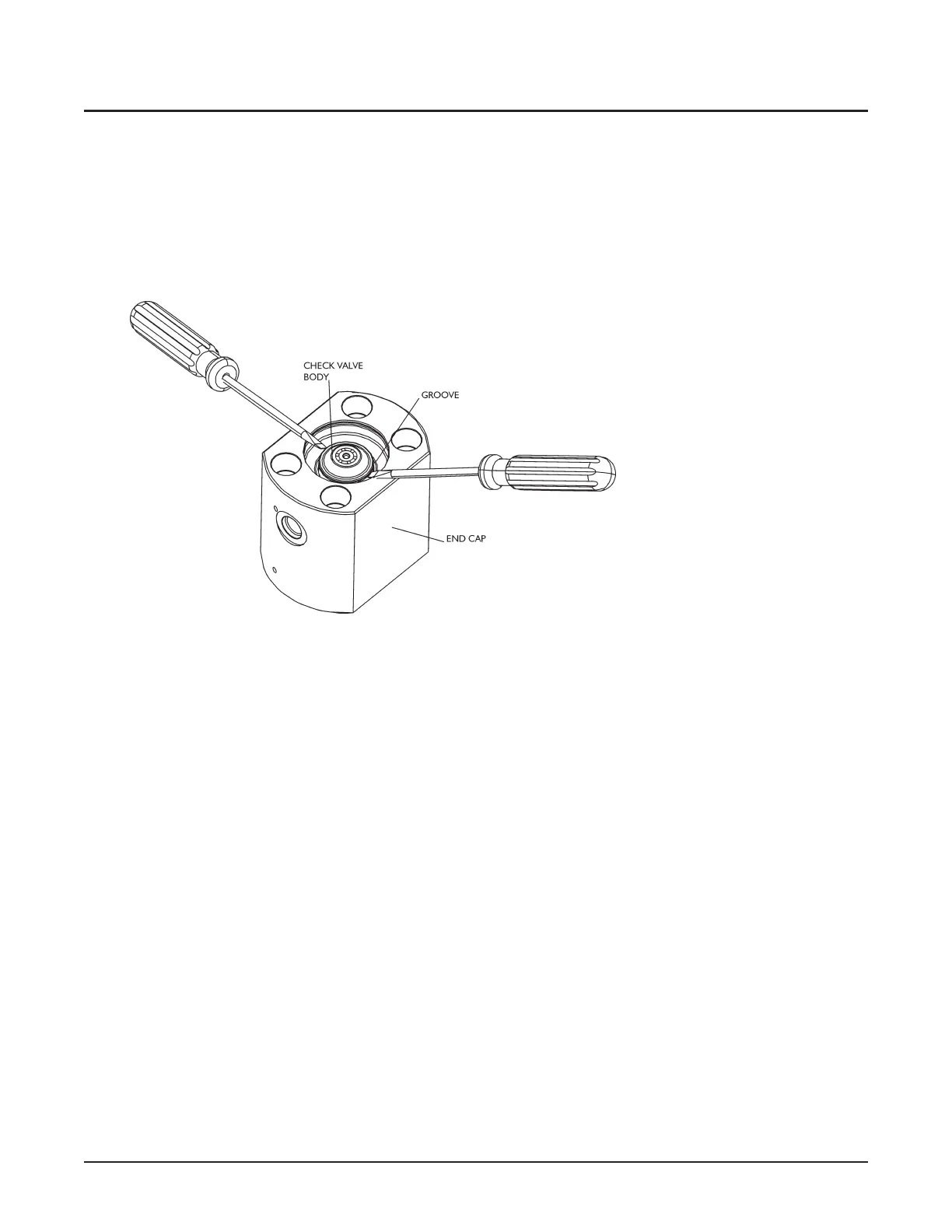
9. Remove the check valve assembly from the end caps
by using two screwdrivers in the circumferential
groove in the OD of the check valve body. Be care
-
ful not to damage the body or the end cap. Remove
the o-ring from the check valve assembly.
10. Place the check valve body in the provided rebuild
clamp.
Note: Do not cover the holes on the outer circum
-
ference of the check valve body to prevent metal
from being introduced into the opening.
11. Loosen the outlet cage.
12. Remove the outlet poppet and guide, outlet poppet
spring, and outlet poppet seat. Discard the poppet,
seat, guide, and spring.
© Flow International Corporation M-416 | 57
CHAPTER 4
Service