Argus E25 MOD II - Operating Instructions
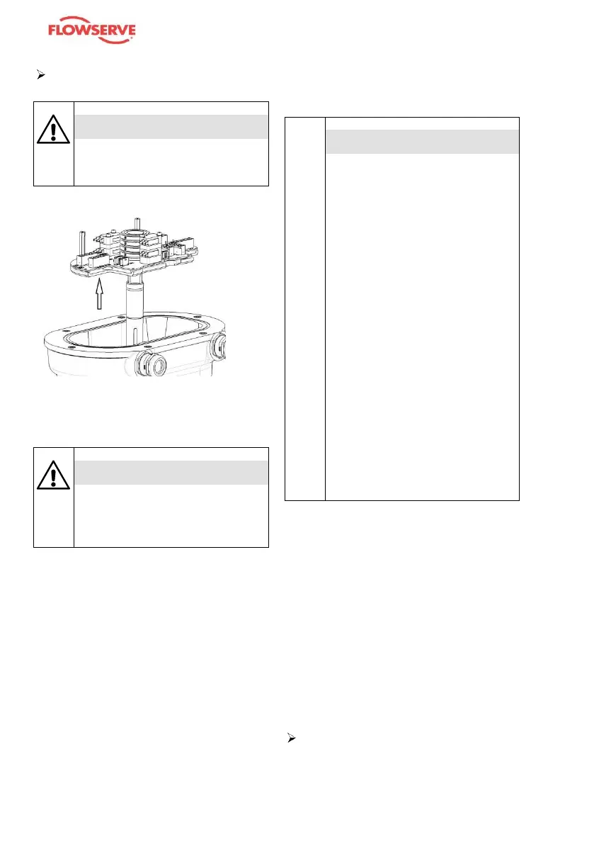
Withdraw the PCB assembly careful-
ly out of the body.
CAUTION
The surface of the operating
shaft must not be damaged.
Replace the limit switch plate and reas-
semble in the reverse order to that
described above.
CAUTION
After replacing the limit switch
plate, the limit switches must
be readjusted.
➢ Make sure there are no hot or haz-
ardous media on the unit or in the
pipeline.
➢ Make sure the unit is disconnected
from all electrical power supplies.
➢ Make sure the plant is switched off
and secured against unauthorised
switching back on.
➢ Make sure the unit and valve, in-
cluding pipelines, have cooled so
that they are no more than hand
warm.
➢ Wear suitable protective clothing
and, when necessary use suitable
protective equipment.
ATTENTION!
Resetting the end-position limit
switches shall only be carried
out in manual operation.
➢ Therefore, use only a suita-
ble tool, e.g. a hand lever,
and follow the regarding
“Emergency manual opera-
tion”.
➢ Whenever the end-position
limit switches are to be re-
set, the unit together with
the valve must be removed
from the pipeline. To dis-
mantle the valve, observe
the separate operating in-
structions.
➢ For setting the end-position
limit switches on units with
multi-way valves or valve
combinations, please con-
tact the manufacturer.
Setting the end-position limit switch-
es
Caution! The following instruction is
only for the "standard" adjustment. For
special adjustment (e.g. for 3-Way
valve) the procedure must be adapted.
Hexagon keys to
EN ISO 4762 / ISO 272
➢ Apply all safety measures as de-
scribed under “Connecting the unit”.
Open the unit’s cover and remove
the cover for the limit switch plate.
Move the unit to its “Open” position
at 90° or 270° (or 0° or 180° for
transverse installation) with the aid
of the hand lever
(see the section