Chapter 1: Hyperion Imaging System Introduction and Specifications
Introduction
8 Hyperion Imaging System: User Guide
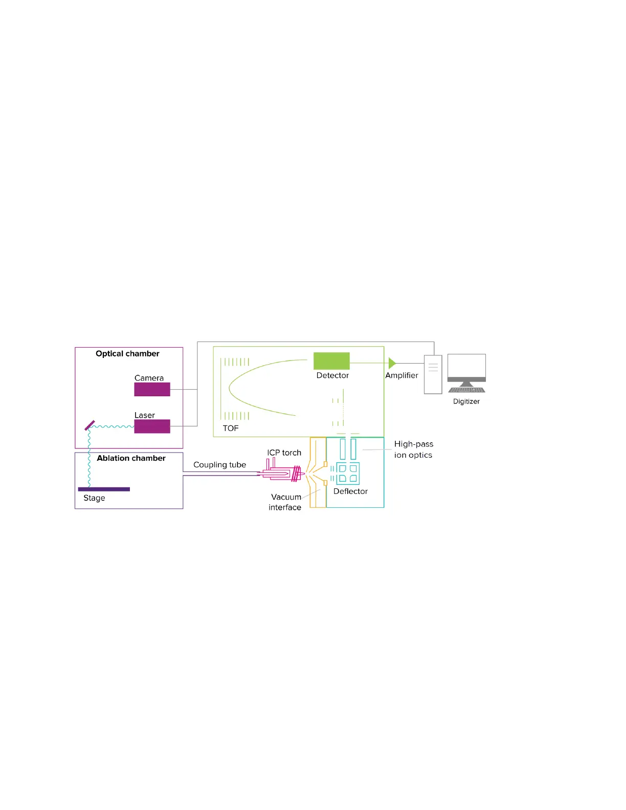
The slide is loaded onto the stage of the ablation chamber and the camera captures the
image from the slide. The system directs a laser beam through the optical components of
the chamber. The laser beam is focused to a 1 µm spot and ablates sample proteins stained
with metal-tagged antibodies on the slide, resulting in aerosol plumes. The plumes are
directed to the Helios ICP Torch, where they are vaporized, atomized, and ionized in the
plasma. The high-pass ion optics remove the low-mass ions that are not of analytical interest
before the ion cloud enters the TOF mass analyzer. The ions enter the TOF mass analyzer in
13 µs intervals (pushes). Ions are separated based on their mass-to-charge ratio and the
detector measures the quantity of each isotope for each plume, corresponding to a single
laser shot, from the sample based on differences in mass instead of wavelength, and at 1 Da
resolution with minimal background.
Acquired data are stored in an MCD file format. In a typical workflow one MCD file is used
for one sample slide which can contain multiple regions of interest (ROIs). MCD files can be
viewed with MCD™ Viewer software. MCD Viewer can also export acquired data as separate
images in a TIFF file format.
Figure 3. Schematic of the Hyperion Imaging System coupled with the Helios system.
86B81BPlume Transients
The material resulting from the laser shot that is directed to the sample slide is referred to as
the plume. The time it takes for a single plume generated as a result of a single laser shot to
be transferred to the Helios system, ionized, and then detected by the detector is defined as
the plume transient time. The duration of the single plume integration is defined as the
plume width. The default value for plume width at a frequency of 200 Hz is 384 pushes (see
Figure 4), which is approximately 5 milliseconds in duration. During manual tuning, the
software can generate a transient curve, which is displayed by opening the Transient
window in the software. When helium flow ramping is set up, the software graphs the dual
counts (number of ions) against time to determine the optimal helium flow required for
effective transient delivery to the Helios instrument with minimal crosstalk (or overlap of
plumes). Autotuning is recommended for optimizing helium flow.