Page 32
FW-E115-P-M_v0203_03_EN.docx
4.4.1 ELECTRICAL SAFETY
Please consult the table with environmental conditions and safety parameters shown at the
beginning of this chapter.
• All wiring must be in accordance with local codes and regulations.
• In case this instrument is connected to a supply by means of a permanent connection a switch or
circuit-breaker shall be included in the installation. This shall be in close proximity to the
equipment and within easy reach of the operator. It shall be marked as the disconnecting device
for the equipment.
• Except for the relay outputs R8 to R11 all connections to the unit shall be low voltage defined as
“SELV” circuit per IEC 60950-1.
• The equipment shall be supplied from a “SELV” circuit defined as per IEC 60950-1.
• A suitable power supply should be considered in end-use equipment. The power supply must be
in compliance with a limited-energy circuit (maximum available current of 8 A). If the power
supply cannot be in compliance with a limited-energy circuit:
• For safety install an overcurrent protection device (such as fuse) with adequate breaking
capacity close to the instrument.
− Fuse type: Time-lag fuse (Approved fuse according to IEC60127-2 and/or UL248-14)
− Fuse rating: Rated current: 5 A
• The installation must comply with national requirements (e.g. in Canada, the Canadian Electrical
Code, C22.1, Part 1 and in USA, the National Electrical Code, NFPA 70, Article 500-series and
ANSI/ISA-RP 12).
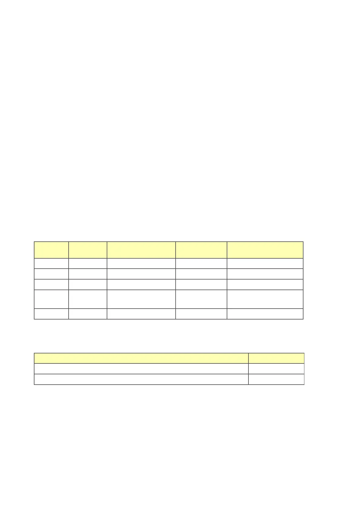
The following supply ratings apply for the various installed options within the E-series product. This
allows for suitable selection of the power supply and overcurrent protection.
(not mentioned options implies no or neglectable influence on the ratings)

 Loading...