Page 33
FW-E115-P-M_v0203_03_EN.docx
4.4.2 VOLTAGE SELECTION SENSOR SUPPLY
Type PB / PX – Pickup element supply
Terminal S3 provides a limited supply voltage of 3.2 V DC (coil signals 1.2V) for the signal output of
the flowmeter. Output impedance is 2700 ohms, power is limited to 3.3 mW under short circuit
conditions.
This voltage MAY NOT be used to power the flowmeters electronics, converters etc, as it will
not provide adequate sustained power ! All energy used by the flowmeters pick-up will
directly influence the battery life-time (type PB). It is strongly advised to use a “zero power”
pickup such as a coil or reed-switch when operating without external power. It is possible to
use some low power NPN or PNP output signals, but the battery life time will be significantly
reduced (consult your distributor).
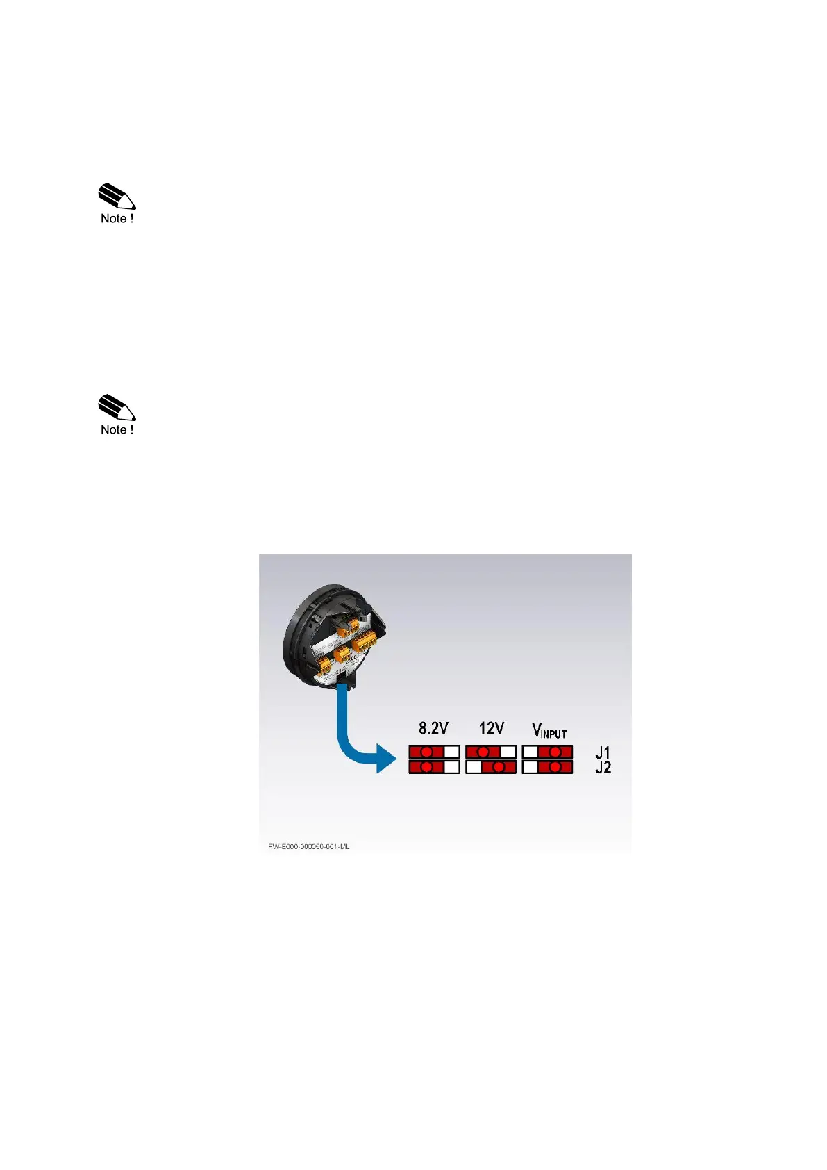
Type PD: Sensor supply: 8.2V – 12V or 24 V (Vin P2 minus 1V) DC
With this option, a supply derived from the input supply becomes available. The output voltage of P3
can be adjusted by means of switches J1 and J2 on the back of the PCB (see figure 12). See the
label or Appendix A, section “Sensor excitation”, for the exact ratings of terminal P3.
• 8.2V DC supply requires an input voltage of 9-27V, maximum output current: 20mA;
12V DC supply requires an input voltage of 13-27V, maximum output current: 30mA;
24V DC supply = V-input – 1V (max 27V), maximum output current: 75mA.
• The output is protected against overload. In case of an overload also the functionality of
the E115-P is affected!
The voltage is selected with the two switches at the rear of the Main Electronics Module (MEM).
The switches are located at the bottom center (type PD):
Fig. 13: Voltage selection – Sensor supply (P3)

 Loading...