Electrical Installation Tester
Operating the Tester
11
Table 6. Display Features (cont.)
No. Annunciator Meaning
Arrows above or below the terminal
indicator symbol indicate reversed
polarity. Check the connection or check
the wiring to correct.
Terminal indicator symbol. A terminal
indicator symbol with a dot () in the
center indicates the terminal is used for
the selected function. The terminals are:
• L (Line)
• PE (Protective Earth)
• N (Neutral)
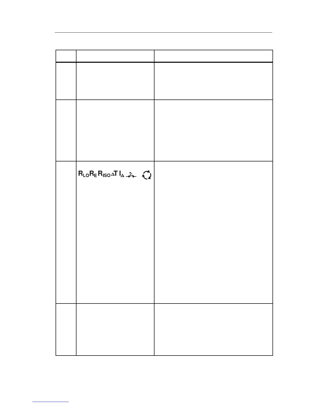
Indicates the selected rotary switch
setting. The measurement value in the
primary display also corresponds to the
switch setting. Rotary switch settings are:
V
Volts
Insulation
Continuity
Loop no trip
Loop hi current trip
RCD trip time
RCD trip current
Earth
Phase Rotation
RCD
Indicates that the measured trip current
(trip current test) or the measured trip
time (trip time test) is according to the
appropriate RCD standard and the fault
voltage is below the selected limit. For
more information, see Maximum Trip
Time Table on page 54.