Input and Channel Configuration
Input Wiring 3
3-5
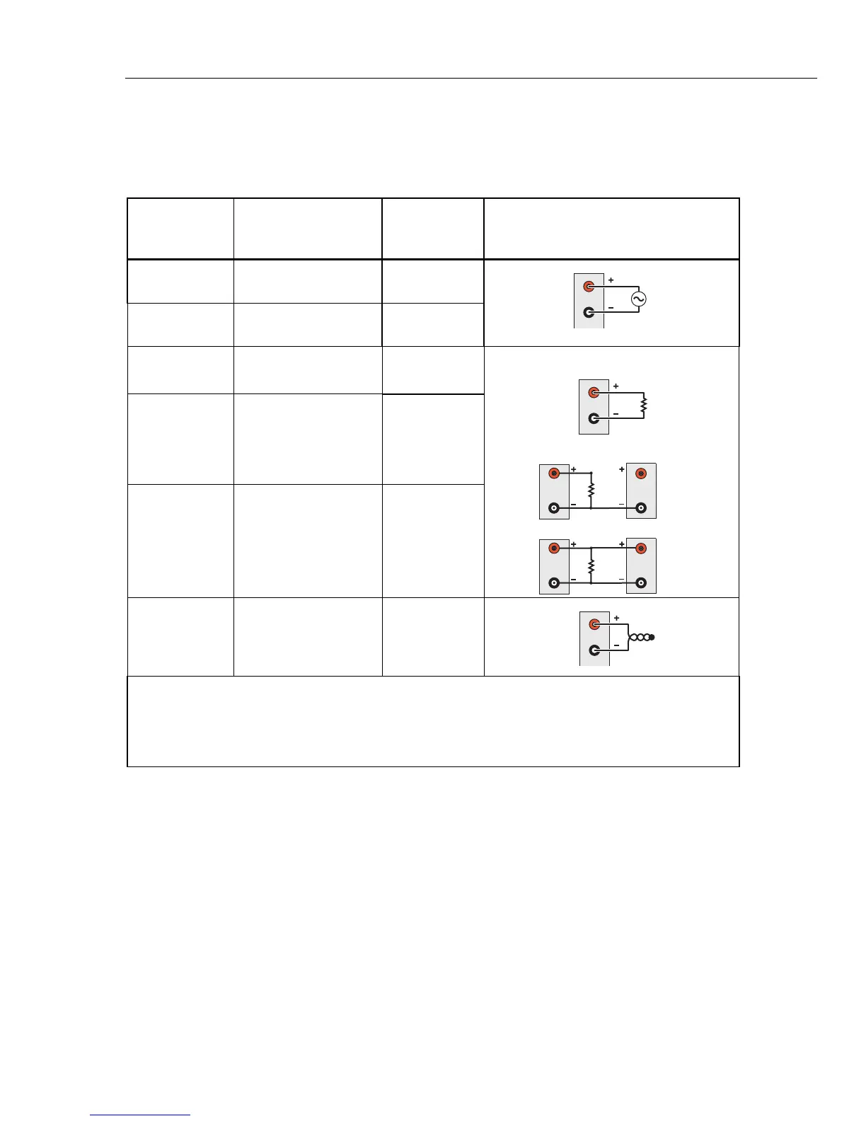
Input Types and Wiring Diagrams
Table 3-1 lists the type of input types the Product can measure and the wiring polarity
that should be used to wire it to the Input Module.
Table 3-1. Types of Inputs
Type of Input Range and Types
Channel
Configuration
Reference
Wiring Polarity
ac and dc
Voltage
Range: 0 V to 300 V
[2]
Page 3-17
H
L
V
ac and dc
Current
[1]
Range: 0 mA to ±100
mA
Page 3-17
Resistance (Ω)
2-Wire or 4-Wire
[3]
Range: 0 Ω to 100 MΩ
Page 3-18
H
L
R
2-Wire
H
Source
Sense
L
R
4-Wire
H
L
H
Source
Sense
L
R
3-Wire
H
L
Platinum
Resistance
Thermometer
(PRT)
2-Wire, 3-Wire or 4-Wire
Types:
• PT385 or PT392
• R0: 0.09 Ω to 1.2 kΩ
Page 3-22
Thermistor
2-Wire or 4-Wire
Types:
• 2.252 kΩ
• 5 kΩ
• 10 kΩ
Page 3-20
Thermocouple
Types: B, C, D, E, G, J,
K, L, M, N, R, S, T, U,
W,
Page 3-19
H
L
Note
[1] − Each Input Module has two terminal sets (mA 21 and mA 22) that are dedicated to current measurements.
[2] − 300 V is for Ch001 only. Other analog channels are 150 V max.
[3] − 100 M
Ω is for Ch001 only. Other analog channels are 10 MΩ Max.
1.888.475.5235info@Fluke-Direct.com
Fluke-Direct.com