Input and Channel Configuration
Mx+B, Alarms, and Channel Options 3
3-31
5. Highlight High or Low then push .
6. Use the numeric keypad to input the limit (
Setpoint).
7. To turn on an alarm output:
a. Highlight
Output the then push .
b. Highlight an alarm output to assign to the channel then push .
Terminal
GND
1
2
3
4
5
6
TRIG
Function
Ground Terminal
Alarm Output 1
Alarm Output 2
Alarm Output 3
Alarm Output 4
Alarm Output 5
Alarm Output 6
External Trigger Input
hcn041.eps
Figure 3-9. Rear-Panel Alarm Outputs
= Low Condition (<0.7 V dc)
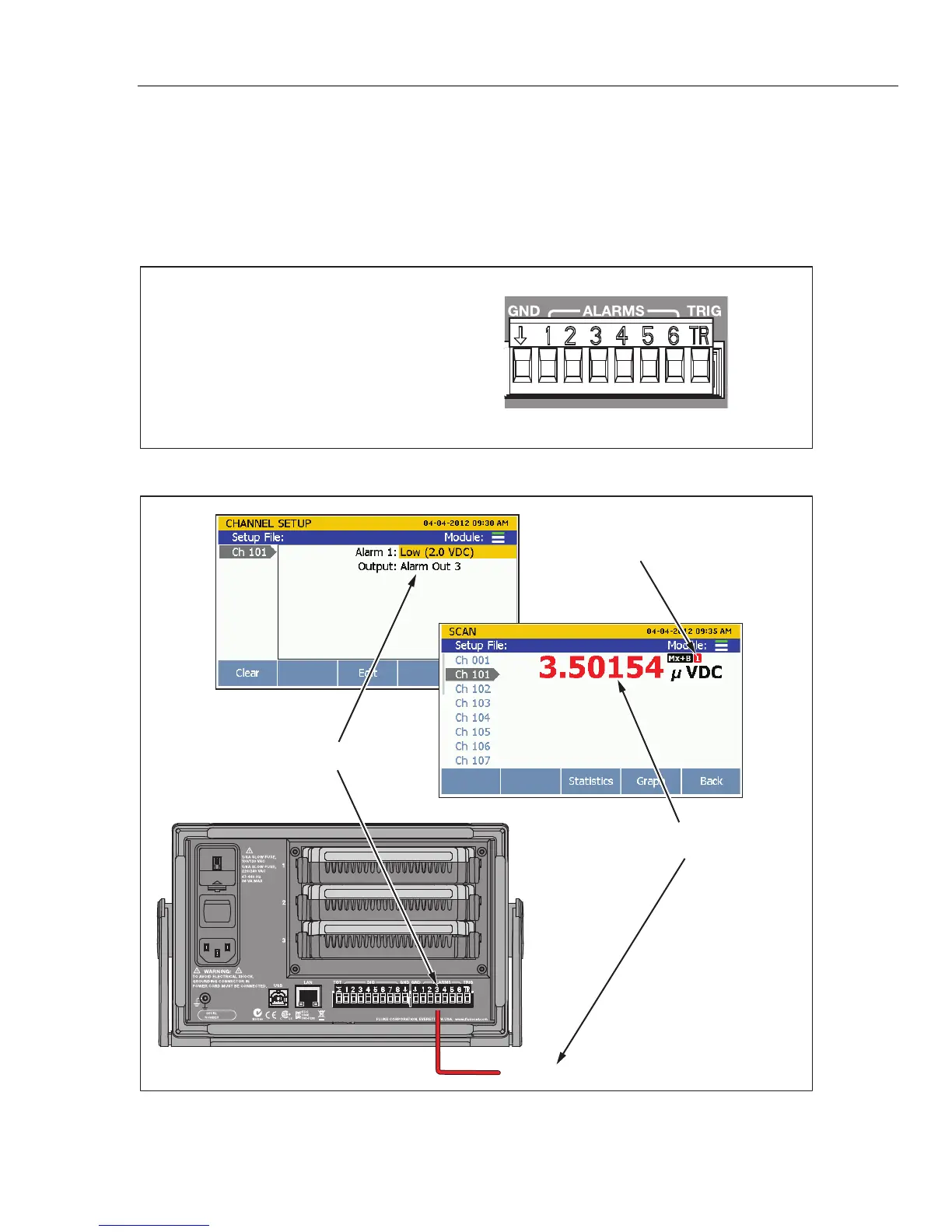
Alarm Setup
Lower-limit exceeded, alarm
output 3 outputs <0.7 V dc
Monitor Screen
Rear View
Alarm output 3 low limit set to 2 V dc
Alarm Indicator
hcn035.eps
Figure 3-10. Alarm Output Example
1.888.475.5235info@Fluke-Direct.com
Fluke-Direct.com