Chapter 3: How to Certify Fiber Cabling
Autotest in Smart Remote Mode
63
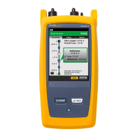
To see the results, limits, and margins for a fiber, tap the
window.
The settings the tester used for the test.
The dashed lines are around the connectors and fiber that are
included in the loss and length results. Gray connectors and
fibers are not included because you used them to set the
reference.
Connector icons show the number you entered for the TOTAL
CONNECTIONS setting on the No. of Connectors/Splices
screen (Figure 15 on page 52). For Figure 19, the TOTAL
CONNECTIONS setting is 4.
The round icon shows the number of splices entered for the
SPLICES setting on the No. of Connectors/Splices screen.
To see help for the screen, tap .
When more than one button shows at the bottom of the screen,
the tester highlights one in yellow to recommend which one to
tap. See “Buttons to Do Tests and Save Results” on page 23.