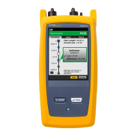
CertiFiber Pro Fiber Optical Loss Test Set
Users Manual
80
The dashed lines are around the connectors and fiber that are
included in the loss and length results. Gray connectors and
fibers are not included because you used them to set the
reference.
Connector icons show the number you entered for the TOTAL
CONNECTIONS setting on the No. of Connectors/Splices
screen (Figure 15 on page 52). For Figure 25, the TOTAL
CONNECTIONS setting is 1.
The round icon shows the number of splices entered for the
SPLICES setting on the No. of Connectors/Splices screen.
To see help for the screen, tap .
When more than one button shows at the bottom of the screen,
the tester highlights one in yellow to recommend which one to
tap. See “Buttons to Do Tests and Save Results” on page 23.
Bi-Directional Tests
A connector or splice can have a different loss when you measure
from the other end of the fiber. Thus, some manufacturers of
fiber cable and components will not give you warranty support
unless you do bi-directional tests. Do bi-directional tests when
they are required by the manufacturer or by your customer.
The tester can automatically do bi-directional tests in Smart
Remote and Loopback modes. To get bi-directional results in Far
End Source mode, do a test from each end of the fiber.
In Smart Remote mode, the tester saves bi-directional results in
two records. Each record contains the results for one fiber for
both directions.
To do a bi-directional test
1 On the home screen, tap the test setup panel, make sure the
correct test is selected on the CHANGE TEST screen, then tap
EDIT.
2 On the TEST SETUP screen, in the Bi-Directional panel, tap the
control to make it show On, then tap SAVE.